Table of Contents
Advertisement
Quick Links
Advertisement
Table of Contents

Related Manuals for Altos R360 F5 SFF


Summary of Contents for Altos R360 F5 SFF
- Page 1 R360 F5 USER’S MANUAL Revision 1.0...
- Page 2 Unless you request and receive written permission from Altos Computer, Inc., you may not copy any part of this document. Information in this document is subject to change without notice. Other products and companies referred to herein are trademarks or registered trademarks of their respective companies or mark holders.
-
Page 3: About This Manual
Preface Preface About this Manual This manual is written for professional system integrators and PC technicians. It provides information for the installation and use of the server. Installation and maintenance should be performed by experienced technicians only. Warnings Special attention should be given to the following symbols used in this manual. Warning! Indicates important information given to prevent equipment/property damage or personal injury. - Page 4 Chapter 1: Introduction Chapter 1 Introduction 1.1 Overview This chapter provides a brief outline of the functions and features of the SuperServer 120U-TNR. The following provides an overview of the specifications and capabilities. System Overview Motherboard X12DPU-6 Chassis 119UH3TS-R1K22P-T Processor Dual P+ (LGA4189) sockets 3rd Gen Intel Xeon Scalable Support 32 DIMM slots, DDR4 RDIMM/LRDIMM or Intel Optane PMem 200 Series*...
-
Page 5: Configuration Options
Chapter 1: Introduction Configuration Options Riser Cards Ultra Riser cards provide network connections and other capabilities. The customer must choose one when purchasing the system. LAN Ports Description No NIC PCIe 4.0 x16 (Internal), four NVMe ports Two RJ45, Intel X710-AT2, Two 10GBaseT PCIe 4.0 x16 (Internal), four NVMe ports Four 10GBaseT... -
Page 6: System Features
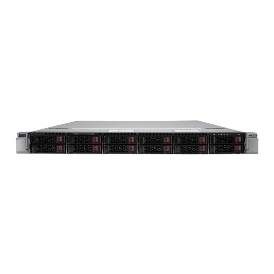
Chapter 1: Introduction 1.2 System Features The following views of the system display the main features. Refer to Appendix B for additional specifications. Front View R360 F5 SFF Control Panel Service/Asset Tag USB 3.0 Port with BMC Password Figure 1-1. Front View... -
Page 7: Drive Carrier Indicators
Chapter 1: Introduction Drive Carrier Indicators Each drive carrier has two LED indicators: an activity indicator and a status indicator. For RAID configurations using a controller, the meaning of the status indicator is described in the table below. For OS RAID or non-RAID configurations, some LED indications are not supported, such as hot spare. - Page 8 Chapter 1: Introduction Control Panel R360 F5 SFF Information LED UID Button/LED NIC LED Power LED Power BMC Reset Figure 1-2. Control Panel Control Panel Features Feature Description The unit identification (UID) button turns on or off the blue light function of the Information UID button/LED LED and a blue LED on the rear of the chassis.
- Page 9 Chapter 1: Introduction Red, solid, with Power LED blinking Fault detected green Blue and red, blinking at 10 Hz Recovery mode UID has been activated locally to locate the Blue, solid server in a rack environment. UID has been activated using the BMC to locate Blue, blinking at 1Hz the server in a rack environment.
-
Page 10: Rear View
Chapter 1: Introduction Rear View USB Ports Power Supplies UID Button/BMC Reset BMC LAN Figure 1-3. System: Rear View System Features: Rear Feature Description Power Supplies Two redundant power supply modules, PWS1 on the left, PWS2 on the right LAN ports; specifications depend on your Ultra riser card option Expansion card slots;... -
Page 11: Power Supply Indicator
Indicates that the power supply has a warning condition and continues to operate. Indicates that the power supply is plugged in, and is in an abnormal state. The Solid Amber system might need service. Please contact Altos technical support. No AC power to modules... -
Page 12: Top View
Chapter 1: Introduction Top View Power Supply Modules SATADOM Ports Dual Processors DIMM Slots System Fans Figure 1-4. System: Top View System Features: Top Feature Description Power Supply Dual redundant modules; see options on a previous page Two Disk-on-Module ports allows for flash cards to be mounted directly on the SATADOM ports Motherboard DIMM slots... -
Page 13: System Architecture
Chapter 1: Introduction 1.3 System Architecture This section shows the locations of the system electrical components, and a block diagram of the overall system. Main Components Riser Card, Left-facing Ultra Riser Card; (options) Riser Card, Right-facing Motherboard X12DPU-6 Storage Backplane BPN-NVMe4-119A-S12 (manual) Figure 1-5. -
Page 14: System Block Diagram
Chapter 1: Introduction System Block Diagram The block diagram below shows the connections and relationships between the subsystems and major components of the overall system. BMC LAN Figure 1-6. System Block Diagram... -
Page 15: Motherboard Layout
Chapter 1: Introduction 1.4 Motherboard Layout Below is a layout of the X12DPU-6 motherboard with jumper, connector and LED locations shown. See the table on the following page for descriptions. For detailed descriptions, pinout information and jumper settings, refer to Chapter 4 or the Motherboard Manual. -
Page 16: Quick Reference
Chapter 1: Introduction Quick Reference Jumper Description Default Setting JBT1 Clear CMOS Open (Normal) JUID UID Enable/System Reset Jumper Pins 1-2 (UID Enabled) Connector Description Onboard CMOS battery COM1 Backplane COM port FAN1 ~ FAN8 CPU/System fan headers FFC (Flat Flexible Cable) connector BMC_LAN Dedicated BMC LAN port (JLAN1) I-SATA 0~3, I-SATA 4~7... -
Page 17: Motherboard Block Diagram
Chapter 1: Introduction Description State: Status LEDM1 BMC Heartbeat LED Blinking Green: BMC Normal LED1 Rear UID (Unit Identifier) LED Solid Blue: Unit Identified Motherboard Block Diagram X12DPU-6 DDR4 RTL8211F COM1 Ultra IO Port A 32MB BIOS SPI FLASH Port B Header PE[5] LPC/eSPI... - Page 18 Chapter 1: Introduction 7+1 PHASE 7+1 PHASE OCuLink x4 OCuLink OCuLink OCuLink OCuLink Figure 1-8. Motherboard Block Diagram...
-
Page 19: Server Installation
Chapter 2: Server Installation Chapter 2 Server Installation 2.1 Overview This chapter provides advice and instructions for mounting your system in a server rack. If your system is not already fully integrated with processors, system memory etc., refer to Chapter 3 for details on installing those specific components. -
Page 20: Rack Precautions
Chapter 2: Server Installation • This product is not suitable for use with visual display workplace devices according to §2 of the German Ordinance for Work with Visual Display Units. Rack Precautions • Ensure that the leveling jacks on the bottom of the rack are extended to the floor so that the full weight of the rack rests on them. - Page 21 Chapter 2: Server Installation Airflow Equipment should be mounted into a rack so that the amount of airflow required for safe operation is not compromised. Mechanical Loading Equipment should be mounted into a rack so that a hazardous condition does not arise due to uneven mechanical loading.
-
Page 22: Installing The Rails
Chapter 2: Server Installation 2.4 Installing the Rails There are a variety of rack units on the market, which may require a slightly different assembly procedure. This rail set fits a rack between 25.6" and 33" deep. The following is a basic guideline for installing the system into a rack with the rack mounting hardware provided. -
Page 23: Installing The Outer Rails Onto The Rack
Chapter 2: Server Installation Installing the Outer Rails onto the Rack Each end of the assembled outer rail includes a bracket with square pegs to fit into your rack holes. If you have an older rack with round holes, these brackets must be removed, and you must use screws to secure the rail to the rack. -
Page 24: Installing The Chassis Into A Rack
Chapter 2: Server Installation 2.5 Installing the Chassis into a Rack Once rails are attached to the chassis and the rack, you can install the server. 1. Pull the middle rail out of the front of the outer rail and make sure that the ball bearing shuttle is locked at the front of the middle rail. -
Page 25: Removing The Chassis From The Rack
Chapter 2: Server Installation Removing the Chassis from the Rack Caution! It is dangerous for a single person to off-load the heavy chassis from the rack without assistance. Be sure to have sufficient assistance supporting the chassis when removing it from the rack. -
Page 26: Maintenance And Component Installation
Chapter 3: Maintenance and Component Installation Chapter 3 Maintenance and Component Installation This chapter provides instructions on installing and replacing main system components. To prevent compatibility issues, only use components that match the specifications and/or part numbers given. Installation or replacement of most components require that power first be removed from the system. -
Page 27: Accessing The System
Chapter 3: Maintenance and Component Installation 3.2 Accessing the System The chassis features a removable top cover, which allows access to the inside of the chassis. Removing the Top Cover 1. Press the two release buttons and slide the cover toward the rear. 2. -
Page 28: Processor And Heatsink Installation
Chapter 3: Maintenance and Component Installation 3.3 Processor and Heatsink Installation The processor (CPU) and processor carrier should be assembled together first to form the processor carrier assembly. This will be attached to the heatsink to form the processor heatsink module (PHM) before being installed onto the CPU socket. Notes: •... -
Page 29: The Processor Carrier Assembly
Chapter 3: Maintenance and Component Installation The Processor Carrier Assembly The processor carrier assembly is comprised of the processor and the processor carrier. 1. Hold the processor with the land grid array (LGA, gold contacts) facing down. Locate the gold triangle at the corner of the processor and the corresponding hollowed triangle on the processor carrier as shown below. - Page 30 Chapter 3: Maintenance and Component Installation 3. Locate the lever on the carrier and, if necessary, press it down as shown below. Lever 4. Align the CPU keys on the processor (A & B) with those on the carrier (a & b) as shown below.
- Page 31 Chapter 3: Maintenance and Component Installation The Processor Heatsink Module (PHM) After creating the processor carrier assembly, mount the heatsink onto the carrier assembly to form the processor heatsink module (PHM). Note: If this is a new heatsink, the thermal grease has been pre-applied. Otherwise, apply the proper amount of thermal grease to the underside of the heatsink.
- Page 32 Chapter 3: Maintenance and Component Installation Installing the PHM into the CPU Socket 1. Remove the plastic protective cover from the CPU socket. Gently squeeze the grip tabs then pull the cover off. CPU Socket with Plastic Protective Cover Grip Tabs...
- Page 33 Chapter 3: Maintenance and Component Installation 2. Locate four threaded fasteners (a, b, c, d) on the CPU socket. Threaded Fastener CPU Socket (a, b, c, d: Threaded Fasteners) CPU Socket Pin1 3. Locate four PEEK nuts (A, B, C, D) and four rotating wires (1, 2, 3, 4) on the heatsink as shown below.
- Page 34 Chapter 3: Maintenance and Component Installation 5. Align nut A (next to the triangles and pin 1) on the heatsink with threaded fastener "a" on the CPU socket. Also align nuts B, C, D on the heatsink with threaded fasteners b, c, d on the CPU socket.
- Page 35 Chapter 3: Maintenance and Component Installation Removing the PHM from the CPU Socket Be sure the system is shut down and all AC power cords are unplugged. 1. Use a t30-bit screwdriver to loosen the four PEEK nuts on the heatsink in the sequence of A, B, C, and D.
- Page 36 Chapter 3: Maintenance and Component Installation Removing the Processor Carrier Assembly from the PHM Detach the four plastic clips (a, b, c, d) on the processor carrier assembly from the four corners of the heatsink (A, B, C, D) as shown below, and lift off the processor carrier assembly. Processor Carrier Assembly Pin 1 Pin 1...
- Page 37 Chapter 3: Maintenance and Component Installation Removing the Processor from the Carrier Assembly Unlock the lever from its locked position and push it upwards to disengage the processor from the carrier as shown below right. Carefully remove the processor from the carrier. Processor Carrier Assembly Lever Note: Handle the processor with care to avoid damage.
-
Page 38: Memory Support
Chapter 3: Maintenance and Component Installation 3.4 Memory Memory Support The X12DPU-6 motherboard has 32 DIMM slots. It supports up to • 8TB (DDR4 only): 3DS Load Reduced DIMM (3DS LRDIMM), 3DS Registered DIMM (3DS RDIMM), or Non-Volatile DIMMs (NV-DIMM) ECC memory with speeds of up to 3200 MHz. •... - Page 39 Chapter 3: Maintenance and Component Installation Guidelines Regarding Mixing DIMMs • All DIMMs must be DDR4 or a mixture of PMem and DDR4. • x4 and x8 DIMMs can be mixed in the same channel. • Mixing of LRDIMMs and RDIMMs is not allowed in the same channel, across different channels, and across different sockets.
- Page 40 Chapter 3: Maintenance and Component Installation DDR4 Memory Population Guidelines The following memory population table was created based on guidelines provided by Intel to support Altos motherboards. Memory Population for DDR4-only Configurations, 32 DIMM Slots CPUs/DIMMs DIMM Slots CPU1: A1 2 CPUs &...
- Page 41 Chapter 3: Maintenance and Component Installation Optane PMem 200 Series For 3rd Gen Intel Xeon Scalable Platinum, Gold and selected Silver processors Symmetric Population for Each CPU with PMem + DDR4 DIMM DDR4 & Modes interl- PMem leve 1 - x4 DDR4 DDR4 DDR4...
- Page 42 Chapter 3: Maintenance and Component Installation PMem Notes • PMem 200 Series are supported on 3rd gen Intel Xeon Scalable Platinum, Gold and se- lected Silver processors. • Do not mix PMem and NVDIMMs within the platform. • For MM, NM/FM ratio is between 1:4 and 1:16. The capacity not used for FM can be used for AD.
-
Page 43: Installing Memory
Chapter 3: Maintenance and Component Installation Installing Memory ESD Precautions Electrostatic Discharge (ESD) can damage electronic components including memory modules. To avoid damaging DIMM modules, it is important to handle them carefully. The following measures are generally sufficient. • Use a grounded wrist strap designed to prevent static discharge. •... -
Page 44: Motherboard Battery
Chapter 3: Maintenance and Component Installation 3.5 Motherboard Battery The motherboard uses non-volatile memory to retain system information when system power is removed. This memory is powered by a lithium battery residing on the motherboard. Replacing the Battery Begin by removing power from the system. -
Page 45: Storage Drives
Chapter 3: Maintenance and Component Installation 3.6 Storage Drives The system supports twelve hot-swap 2.5" storage drives in hybrid bays. SATA support is default. SAS support can be afforded with an optional controller card and cables. NVMe support also requires additional cables. For compatible storage drives, see the X12DPU-6 motherboard page. -
Page 46: Hot-Swap For Nvme Drives
Chapter 3: Maintenance and Component Installation Hot-Swap for NVMe Drives Altos Ultra servers support NVMe surprise hot-swap. For even better data security, NVMe orderly hot-swap is recommended. NVMe drives can be ejected and replaced remotely using the BMC Dashboard. Note: If you are using VROC, see the VROC section in this manual instead. -
Page 47: Checking The Temperature Of An Nvme Drive
Chapter 3: Maintenance and Component Installation Checking the Temperature of an NVMe Drive There are two ways to check using the BMC Dashboard. Checking a Drive • BMC Dashboard > Server Health > NVMe SSD – Shows the temperatures of all NVMe drives. -
Page 48: Air Shrouds
Chapter 3: Maintenance and Component Installation Air Shrouds Air shrouds concentrate airflow to maximize fan efficiency. The air shroud does not require screws to install. Installing an Air Shroud 1. Position the air shroud in the chassis as illustrated below. 2. -
Page 49: Power Supply Leds
• Solid Amber: When illuminated, indicates that the power supply is plugged in, and is in an abnormal state. The system might need service. Please contact Altos technical support. Changing the Power Supply Module: 1. Unplug the AC cord from the module to be replaced. -
Page 50: Pci Expansion Slots
Chapter 3: Maintenance and Component Installation 3.9. PCI Expansion Slots This system includes riser cards that allow for expansion cards. Figure 3-9. Expansion Card Slots Riser Cards This system include riser cards that provide PCIe capabilities—one Ultra Riser card (described Section 1.1), one right-facing WIO riser card, and one left-facing WIO card. - Page 51 Chapter 3: Maintenance and Component Installation Installing a Full-Height Expansion Card 1. Power down the system as described in section 3.1 and remove the cover. 2. Pull out the bracket and sections of the chassis in the rear. Figure 3-10. Riser Card Bracket and Expansion Slots 3.
- Page 52 Chapter 3: Maintenance and Component Installation Expansion Cards <new bracket coming soon > Internal Expansion Card Figure 3-11. Expansion cards Installed...
-
Page 53: Internal Expansion Card
Internal Expansion Card For most models, the pre-installed Ultra riser card that provides LAN ports also offers another internal low profile card slot for a Altos SAS controller. Installing the Internal Expansion Card 1. Power down the system as described in section 3.1 and remove the cover. -
Page 54: Cable Routing
Chapter 3: Maintenance and Component Installation 3.10 Cable Routing Use this section to route or reroute cables. Proper routing is important to maintain airflow through the system. SAS cable routing depends on the model and position of the SAS controller card, so routing is not shown here. SATA Cable Backplane Power Cable Front Panel USB Cable... -
Page 55: Motherboard Connections
Chapter 4: Motherboard Connections Chapter 4 Motherboard Connections This section describes the connections on the motherboard and provides pinout definitions. Note that depending on how the system is configured, not all connections are required. The LEDs on the motherboard are also described here. A motherboard layout indicating component locations may be found in Chapter 1. -
Page 56: Headers And Connectors
Chapter 4: Motherboard Connections 4.2 Headers and Connectors Fan Headers There are eight fan headers on the motherboard, (FAN1-8). These are 4-pin fan headers, although pins 1-3 are backward compatible with traditional 3-pin fans. Four-pin fans allow fan speeds to be controlled by Thermal Management in the BMC. When using the Thermal Management setting, use all 3-pin fans or all 4-pin fans. - Page 57 The JTPM1 header is used to connect a Trusted Platform Module (TPM), which is available from Altos. A TPM connector is a security device that supports encryption and authentication in hard drives. It allows the motherboard to deny access if the TPM associated with the storage drive is not installed in the system.
- Page 58 Chapter 4: Motherboard Connections RAID Key Header An Intel VROC RAID Key header is located at JRK1. It supports VMD used in creating optional advanced NVMe RAID configurations. RAID Key Header Pin Definitions Pin# Definition Ground RAID_KEY_PU Ground PCH_RAID_KEY VROC Key Note: This drawing is for illustration only.
- Page 59 Chapter 4: Motherboard Connections Control Panel JF1 contains header pins for various control panel connections. See the figure below for the pin locations and definitions of the control panel buttons and LED indicators. All JF1 wires have been bundled into a single cable to simplify this connection. Make sure the red wire plugs into pin 1 as marked on the motherboard.
- Page 60 Chapter 4: Motherboard Connections Power Fail LED The Power Fail LED connection is located on pins 5 and 6 of JF1. Power Fail LED Pin Definitions (JF1) Pin# Definition 3.3V PWR Supply Fail Overheat (OH)/Fan Fail Connect an LED cable to pins 7 and 8 of JF1 to use the Overheat/Fan Fail LED connections. The LED on pin 8 provides warnings of overheat or fan failure.
- Page 61 Chapter 4: Motherboard Connections Power LED The Power LED connection is located on pins 15 and 16 of JF1. Power LED Pin Definitions (JF1) Pin# Definition 3.3V Power LED NMI Button The non-maskable interrupt button header is located on pins 19 and 20 of JF1. NMI Button Pin Definitions (JF1) Pin#...
-
Page 62: Input/Output Ports
Chapter 4: Motherboard Connections 4.3 Input/Output Ports See the figure below for the locations and descriptions of the I/O ports on the rear of the motherboard. Figure 4-2. Rear I/O Ports Rear I/O Ports Description Description USB0 (3.0) COM1 USB1 (3.0) UID Switch BMC Dedicated LAN LAN Ports... - Page 63 Chapter 4: Motherboard Connections 4.4 Jumpers Explanation of Jumpers To modify the operation of the motherboard, jumpers are used to choose between optional settings. Jumpers create shorts between two pins to change the function associated with it. Pin 1 is identified with a square solder pad on the printed circuit board. See the motherboard layout page for jumper locations.
-
Page 64: Led Indicators
Chapter 4: Motherboard Connections 4.5 LED Indicators Network LAN LEDs The Ethernet ports each have two LEDs. One LED indicates activity when flashing green. The other may be green, amber or off to indicate the speed of the connection. Speeds noted in Chapter 1. -
Page 65: Storage Ports
SATA 0-3, S-SATA 4, S-SATA 5) on the motherboard. These SATA ports are supported by the Intel PCH C621 chipset. S-SATA 4/S-SATA 5 can be used with Altos SuperDOMs which are orange SATA DOM connectors with power pins built in, and do not require external power cables. - Page 66 USB/SATA DVD drive, or a USB flash drive, or the BMC KVM console. 2. Retrieve the proper RST/RSTe driver. Go to the Altos web page for your motherboard and click on "Download the Latest Drivers and Utilities", select the proper driver, and copy it to a USB flash drive.
- Page 67 Chapter 5: Software 4. During Windows Setup, continue to the dialog where you select the drives on which to install Windows. If the disk you want to use is not listed, click on “Load driver” link at the bottom left corner. Figure 5-2.
-
Page 68: Driver Installation
Chapter 5: Software 5.2 Driver Installation After accessing the website, go into the CDR_Images (in the parent directory of the above link) and locate the ISO file for your motherboard. Download this file to to a USB flash drive or a DVD. -
Page 69: Optional Components
Chapter 6: Optional Components 5.3 BMC The motherboard provides remote access, monitoring and management through the baseboard management controller (BMC) and other management controllers distributed among different system modules. Chapter 6 Optional Components This chapter describes alternate configurations and optional system components. Optional Parts Storage drive options Power options... - Page 70 Chapter 6: Optional Components 2000 PWS-2K08A-1R Titanium 1300 DC PWS-1K30D-1R Not applicable...
-
Page 71: Cable Management Arm
Chapter 6: Optional Components 6.3 Cable Management Arm The system supports a cable management arm (CMA), which keeps the rear cables organized and clear of the rail mechanisms when the system is extended out the front of the rack for maintenance. - Page 72 Chapter 6: Optional Components Figure 6-2. Installing the Connectors 3. Slide CMA connector #3 forward onto the two posts on the rear of the left middle rail. It snaps into place. 4. For CMA connector #4, align the metal tabs with the slots on the rear of the left outer rail and push it forward.
- Page 73 Chapter 6: Optional Components 6.4 TPM Security Module SPI capable TPM 2.0 (or 1.2) with Infineon 9670 controller, vertical form factor The JTPM1 header is used to connect a Trusted Platform Module (TPM). A TPM is a security device that supports encryption and authentication in hard drives. It enables the motherboard to deny access if the TPM associated with the hard drive is not installed in the system.
-
Page 74: Requirements And Restrictions
Chapter 6: Optional Components 6.5 Intel Virtual RAID on CPU (VROC) Intel ® Virtual RAID on CPU (Intel VROC) is an enterprise RAID solution for NVMe SSDs directly attached to Intel Xeon Scalable processors. Intel Volume Management Device (VMD) is an integrated controller inside the CPU PCIe root complex. - Page 75 Chapter 6: Optional Components Hardware Key The Intel VROC hardware key is a license key that detects the Intel VROC SKU and activates the function accordingly. The key must be plugged into the Altos motherboard (connector JRK1). The key options are: VROC Package...
- Page 76 Chapter 6: Optional Components Configuring NVMe RAID Manually RAID for NVMe SSDs is enabled by default when Intel VROC Raid Key is populated. It may be managed manually through the UEFI BIOS. 1. Reboot the server and press [DEL] key to access the BIOS options. 2.
- Page 77 Chapter 6: Optional Components Figure 6-8. BIOS, Manual Mode (Example—your server may look different.) 3. Select the desired PStack# to Enable or Disable the corresponding Intel VMD controller Figure 6-9. BIOS, Enabling VMD for Pstack0...
- Page 78 Chapter 6: Optional Components 4. Select the desired PCIe slot to Enable or Disable Intel VMD functionality according to the current hardware configuration being used. Hot Plug Capability can also be Enabled or Disabled. Figure 6-10. BIOS, Enabling VMD Functionality per Slot 5.
- Page 79 Chapter 6: Optional Components Figure 6-12. BIOS, Enabling CPU2 Example 6. Press [F4] to save the configuration and reboot the system and press [DEL] to enter BIOS. Note: Disabling the VMD controller without first deleting the associated existing RAID volume can lead to unexpected behavior. This action is strongly not recommended. Note: The effects of physically changing or swapping a CPU on the VMD controller enablement has not yet been thoroughly tested or documented.
- Page 80 Chapter 6: Optional Components 10. If cross-controller RAID is required, select Enable RAID spanned over VMD Controller. Figure 6-13. Created Volume without Figure 6-14. Created Volume with enabling RAID spanned over VMD enabling RAID spanned over VMD controller controller 11. Select specific disks for RAID with an [X]. •...
-
Page 81: Status Indications
Chapter 6: Optional Components Status Indications An LED indicator on the drive carrier shows the RAID status of the drive. Drive Carrier Status LED Indicator Status State (red) Normal function Locating 4 Hz blink Fault Solid on Rebuilding 1 Hz Blink IBPI SFF 8489 Defined Status LED States Hot Swap Drives Intel VMD enables hot-plug and hot-unplug for NVMe SSDs, whether from Intel or other... -
Page 82: Appendix A: Warning Statements
Appendix A: Warning Statements Appendix A Standardized Warning Statements for AC Systems About Standardized Warning Statements The following statements are industry standard warnings, provided to warn the user of situations which have the potential for bodily injury. Should you have questions or experience difficulty, Warning Definition Warning! This warning symbol means danger. - Page 83 Appendix A: Warning Statements Warnung WICHTIGE SICHERHEITSHINWEISE Dieses Warnsymbol bedeutet Gefahr. Sie befinden sich in einer Situation, die zu Verletzungen führen kann. Machen Sie sich vor der Arbeit mit Geräten mit den Gefahren elektrischer Schaltungen und den üblichen Verfahren zur Vorbeugung vor Unfällen vertraut. Suchen Sie mit der am Ende jeder Warnung angegebenen Anweisungsnummer nach der jeweiligen Ü...
-
Page 84: Installation Instructions
Appendix A: Warning Statements . ز ذ ح ت ! ز ط خ ع ز ه ز ل ا ا ذ ه ة ذ س ج ة ب ا ص ا ف ب ب س ت ت ى أ ك ي و... -
Page 85: Circuit Breaker
Appendix A: Warning Statements Warnung Vor dem Anschließ en des Systems an die Stromquelle die Installationsanweisungen lesen. ¡Advertencia! Lea las instrucciones de instalación antes de conectar el sistema a la red de alimentación. Attention Avant de brancher le système sur la source d'alimentation, consulter les directives d'installation. מתח... - Page 86 Appendix A: Warning Statements Warnung Dieses Produkt ist darauf angewiesen, dass im Gebäude ein Kurzschluss- bzw. Ü berstromschutz installiert ist. Stellen Sie sicher, dass der Nennwert der Schutzvorrichtung nicht mehr als: 250 V, 20 A beträgt. ¡Advertencia! Este equipo utiliza el sistema de protección contra cortocircuitos (o sobrecorrientes) del edificio.
-
Page 87: Power Disconnection Warning
Appendix A: Warning Statements Power Disconnection Warning Warning! The system must be disconnected from all sources of power and the power cord removed from the power supply module(s) before accessing the chassis interior to install or remove system components. 電源切断の警告 システムコンポーネントの取り付けまたは取り外しのために、シャーシー内部にアクセスするには、... -
Page 88: Equipment Installation
Appendix A: Warning Statements חשמלי ניתוק מפני אזהרה אזהר החשמלי כבל את להסיר ויש החשמל מקורות מכל המערכת את לנתק יש ה רכיבים הסרת או התקנת לצורך מארז ה של הפנימי לחלק גישה לפני מהספק اد مد ا ة د ح... -
Page 89: Restricted Area
Appendix A: Warning Statements ¡Advertencia! Solamente el personal calificado debe instalar, reemplazar o utilizar este equipo. Attention Il est vivement recommandé de confier l'installation, le remplacement et la maintenance de ces équipements à des personnels qualifiés et expérimentés. אזהרה הציוד עבור... - Page 90 Appendix A: Warning Statements Warnung Diese Einheit ist zur Installation in Bereichen mit beschränktem Zutritt vorgesehen. Der Zutritt zu derartigen Bereichen ist nur mit einem Spezialwerkzeug, Schloss und Schlüssel oder einer sonstigen Sicherheitsvorkehrung möglich. ¡Advertencia! Esta unidad ha sido diseñada para instalación en áreas de acceso restringido. Sólo puede obtenerse acceso a una de estas áreas mediante la utilización de una herramienta especial, cerradura con llave u otro medio de seguridad.
-
Page 91: Battery Handling
Appendix A: Warning Statements Battery Handling Warning! There is the danger of explosion if the battery is replaced incorrectly. Replace the battery only with the same or equivalent type recommended by the manufacturer. Dispose of used batteries according to the manufacturer's instructions 電池の取り扱い... -
Page 92: Redundant Power Supplies
Appendix A: Warning Statements فعليل صحيحة غري بطريقة البطارية اسحبذال حالة يف انفجار من خطر هناك البطارية اسحبذال املصنعة الرشمة به أوصث مام يعادلها ما أو النىع بنفس فقط الصانعة الرشمة لحعليامت وفقا املسحعملة البطاريات من جخلص 경고! 배터리가 올바르게 교체되지 않으면 폭발의 위험이 있습니다. 기존 배터리와 동일하거나... - Page 93 Appendix A: Warning Statements ¡Advertencia! Puede que esta unidad tenga más de una conexión para fuentes de alimentación. Para cortar por completo el suministro de energí a, deben desconectarse todas las conexiones. Attention Cette unité peut avoir plus d'une connexion d'alimentation. Pour supprimer toute tension et tout courant électrique de l'unité, toutes les connexions d'alimentation doivent être débranchées.
-
Page 94: Backplane Voltage
Appendix A: Warning Statements Backplane Voltage Warning! Hazardous voltage or energy is present on the backplane when the system is operating. Use caution when servicing. バックプレーンの電圧 システムの稼働中は危険な電圧または電力が、バックプレーン上にかかっています。修 理する際には注意ください。 警告 当系统正在进行时,背板上有很危险的电压或能量,进行维修时务必小心。 警告 當系統正在進行時,背板上有危險的電壓或能量,進行維修時務必小心。 Warnung Wenn das System in Betrieb ist, treten auf der Rückwandplatine gefährliche Spannungen oder Energien auf. -
Page 95: Comply With Local And National Electrical Codes
Appendix A: Warning Statements ىل ع ة ملىجىد ا ة ق لطا ا و أ ئ ي ا ب كهز ل ا ر لتيا ا ه م طز خ ك هنا هذا خدمة عند حذرا كه يعمل النظام يكىن عندما لىحة... -
Page 96: Product Disposal
Appendix A: Warning Statements הארצי החשמל חוקי תיאום אזהרה והארציים המקומיים החשמל לחוקי תואמת יות לה חייבת הציוד התקנת لتعلقة م ا ىطىية ل ا و لحلية م ا ه ي و للقىا ميتثل ن أ يجب ية ئ ا ب كهر... -
Page 97: Hot Swap Fan Warning
Appendix A: Warning Statements Attention La mise au rebut ou le recyclage de ce produit sont généralement soumis à des lois et/ou directives de respect de l'environnement. Renseignez-vous auprès de l'organisme compétent. המוצר סילוק אזהרה המדינה וחוקי להנחיות בהתאם להיות חייב... - Page 98 Appendix A: Warning Statements Warnung Gefährlich Bewegende Teile. Von den bewegenden Lüfterblätter fern halten. Die Lüfter drehen sich u. U. noch, wenn die Lüfterbaugruppe aus dem Chassis genommen wird. Halten Sie Finger, Schraubendreher und andere Gegenstände von den Ö ffnungen des Lüftergehäuses entfernt.
- Page 99 Appendix A: Warning Statements buurt van de openingen in de ventilatorbehuizing.
-
Page 100: Power Cable And Ac Adapter
Verbindungskabeln, Stromkabeln und/oder Adapater, die Ihre örtlichen Sicherheitsstandards einhalten. Der Gebrauch von anderen Kabeln und Adapter können Fehlfunktionen oder Feuer verursachen. Die Richtlinien untersagen das Nutzen von UL oder CAS zertifizierten Kabeln (mit UL/CSA gekennzeichnet), an Geräten oder Produkten die nicht mit Altos gekennzeichnet sind. - Page 101 Appareils électroménagers et la Loi sur la Sécurité Matériel interdit l'utilisation de câbles certifies- UL ou CSA (qui ont UL ou CSA indiqué sur le code) pour tous les autres appareils électriques sauf les produits désignés par Altos seulement. םילבכ...
- Page 102 다른 케이블이나 어댑터를 사용하면 오작동이나 화재가 발생할 수 있습니다. 전기 용품 안전법은 UL 또는 CSA 인증 케이블 (코드에 UL / CSA가 표시된 케이블)을 Altos 가 지정한 제품 이외의 전기 장치에 사용하는 것을 금지합니다. Stroomkabel en AC-Adapter Waarschuwing! Bij het aansluiten van het Product uitsluitend gebruik maken van de geleverde Kabels of een andere geschikte aan te schaffen Aansluitmethode, deze moet altijd voldoen aan de lokale voorschriften en veiligheidsnormen, inclusief de juiste kabeldikte en stekker.
-
Page 103: System Specifications
Appendix B: System Specifications Appendix B System Specifications Processors Dual 3rd Gen Intel Xeon Scalable processors in a P+ (LGA4189) socket with up to 40 cores and the thermal design power (TDP) of up to 270W Note: Refer to the motherboard specifications pages on our website for updates to supported processors. Chipset Intel PCH C621A (LBG-R) BIOS... - Page 104 Appendix B: System Specifications Operating Environment Operating Temperature: 10º to 35º C (50º to 95º F) Non-operating Temperature: -40º to 60º C (-40º to 140º F) Operating Relative Humidity: 8% to 90% (non-condensing) Non-operating Relative Humidity: 5% to 95% (non-condensing) Regulatory Compliance FCC, ICES, CE, UKCA, VCCI, RCM, NRTL, CB Certified Safety Models...
Need help?
Do you have a question about the R360 F5 SFF and is the answer not in the manual?
Questions and answers