Table of Contents
Advertisement
Index
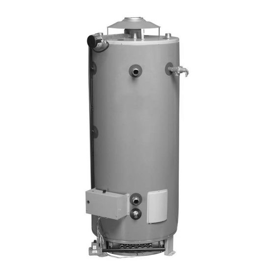
Commercial Gas
Water Heater
Installation
Instructions and
Use & Care Guide
for models with prefix DCG and ADCG
To obtain technical, warranty or service assistance during
or after the installation of this water heater, call toll free:
1-800-456-9805
When calling for assistance, please have the following
information ready:
1. Model number
2. 7 digit product number
3. Serial number
4. Date of installation
5. Place of purchase
Table of Contents . . . . . . . . . . . . . . . . . . . . . . . . . . 2
71681 REV.A 03-09
Advertisement
Table of Contents

Subscribe to Our Youtube Channel
Related Manuals for American Water Heater 71681


Summary of Contents for American Water Heater 71681
-
Page 1: Water Heater Safety
4. Date of installation 5. Place of purchase Table of Contents ......2 71681 REV.A 03-09... -
Page 2: Table Of Contents
what can happen if the instructions are not followed. Table of Contents Water Heater Safety Installation Instructions Unpacking the Water Heater ..... . 3 Installation Requirements Site Location . -
Page 3: Installation Instructions
Index INSTALLATION INSTRUCTIONS Consumer Information This water heater is design-certified by CSA International as a Category I, non-direct vented water heater which takes its combustion air either from the installation area or from air ducted to the unit from the outside. -
Page 4: Installation Requirements
Index FLAMMABLE VAPORS FLAMMABLES Vapors from flammable liquids will explode and catch fire causing death or severe burns. Do not use or store flammable products such as gasoline, solvents or adhesives in the same room or area near the water heater. -
Page 5: Clearances And Accessibility
Index Important: The water heater should be located in an area where leakage of the tank or connections will not result in dam- age to the area adjacent to the water heater or to lower floors of the structure. Due to the normal corrosive action of the water, the tank will eventually leak after an extended period of time. -
Page 6: Combustion Air Supply And Ventilation
Index COMBUSTION/VENT PIPE SYSTEM Carbon Monoxide Hazard Follow all instructions to locate and install the vent pipe system. Instructions can be found in this manual, in state or local codes (or the authority having jurisdiction), or in the absence of such, the National Fuel Gas Code, ANSI Z223.1, NFPA 54, Latest Edition. -
Page 7: Air Requirements
Index Air Requirements An adequate air supply shall be provided for combustion and ventilation of this water heater. An insufficient supply can result in poor combustion and possible sooting of the burner, combustion chamber or flue passageway. This may present a potential fire hazard or could create a serious health hazard by producing carbon monoxide. - Page 8 Index Air Opening Requirements (a) EQUIPMENT LOCATED IN CONFINED SPACES; ALL AIR FROM INSIDE THE BUILDING. Two permanent openings (top and bottom) shall be provided connecting the confined space (e.g., closet/small room) with the unconfined space. Each opening shall have a free area of one square inch per 1,000 BTU/hour (22 cm²/kW) input of all appliances in the confined space, but not less than 100 square inches (645 cm²).
- Page 9 Index Draft Hood/Damper Installation Do not operate water heater with damper in closed position, it must be in the open position during water heater operation. Do not negate the action of any existing safety or operational controls. Install the supplied draft hood and damper on the flue outlet collar.
-
Page 10: Water System Piping
Index WATER SYSTEM PIPING Piping Installation Piping, fittings, and valves should be installed according to the installation drawing (Figure 4). If the indoor installation area is subject to freezing temperatures, the water piping must be protected by insulation. Water supply pressure should not exceed 80% of the work- ing pressure of the water heater. - Page 11 Index Figure 6: Commercial Unit with Auxiliary Booster Heater - Two Temperature (With or Without Building Recirculation) Outlet Boosted Temperature Shut-off valve Thermometer Temperature and Pressure Relief Valve Typical Booster Heater Shut-off valve Figure 7: Commercial Unit with Auxiliary Storage Heater - Forced Circulation With or Without Building Recirculation - Front Inlet/Outlet Connections Shut-off valve Heater...
-
Page 12: Closed System/Thermal Expansion
Index Figure 8: Commercial Unit with Auxiliary Storage Heater - Forced Circulation With or Without Building Recirculation - Top Inlet/Outlet Connections Outlet Boosted Temperature Thermometer Thermometer Pre-Heated Water to the Booster Shut-off valve Typical Booster Heater Please note the following: DO NOT install this water heater with iron piping. -
Page 13: Temperature And Pressure Relief Valve
Index Temperature and Pressure Relief Valve Explosion Hazard If the temperature and pressure relief valve is dripping or leaking, have a qualified service technician replace it. • Do not plug valve. • Do not remove valve. Failure to follow these instructions can result in death or explosion. -
Page 14: Gas Supply And Piping
Index GAS SUPPLY AND PIPING Explosion Hazard Use a new AGA or CSA approved gas supply line. Install a shut-off valve. Do not connect a natural gas water heater to a L.P. gas supply. Do not connect a L.P. gas water heater to a natural gas supply. -
Page 15: Gas Pressure Testing
Index Gas Pressure Testing Important: This water heater and its gas connection must be leak tested before placing the appliance in operation. • If the code requires the gas lines to be tested at a pressure of 14” W.C. or greater, the water heater and its manual shut-off valve must be disconnected from the gas supply piping system and the line capped. -
Page 16: Electrical Connections
Index ELECTRICAL CONNECTIONS If you lack the necessary skills required to properly install the electrical wiring to this water heater, do not proceed but have a qualified service technician perform the installation. When making the electrical connections, always make sure: •... -
Page 17: Wiring Diagram
Index WIRING DIAGRAM... -
Page 18: Installation Checklist
Index INSTALLATION CHECKLIST Water Heater Location Requirements • Centrally located with the water piping system. Located as close to the gas piping and vent pipe system as possible. • Located indoors and in a vertical position. Protected from freezing temperatures. •... -
Page 19: Operating Your Water Heater
Index OPERATING YOUR WATER HEATER Read and understand these directions thoroughly before attempting to operate the water heater (see Lighting Instructions on page 20). Check the data plate on the front of the water heater for the correct gas. Do not use this water heater with any gas other than the one listed on the data plate. -
Page 20: Operating Instructions
Index 1. STOP! Read the safety information above on this label. 2. Turn off all electric power to the appliance. 3. Set the thermostat to the lowest setting. 4. This appliance is equipped with an ignition device which automatically lights the pilot. Do not try to light the pilot by hand. -
Page 21: Operational Conditions
Index Emergency Shut Down Important: If overheating occurs or the gas supply fails to shut off, close the manual gas supply valve and turn the gas control knob to the off position. Turn off the electrical supply to the unit and close the cold water supply valve. -
Page 22: Maintenance Of Your Water Heater
Index MAINTENANCE OF YOUR WATER HEATER Draining and Flushing It is recommended that the tank be drained and flushed every 6 months to remove sediment which may buildup during operation. Note: Warranty is null and void in the event lime & scale deposits are allowed to exceed two inches in depth. -
Page 23: Anode Rod Inspection
Index Pilot Burner and Main Burner Assembly Inspection To access the pilot burner and main burner for inspec- tion: 1. Turn off gas at main shutoff valve and turn off electrical power. 2. Disconnect the gas supply line from the gas valve. 3. -
Page 24: Trouble Shooting Chart
Does pilot light shrink or go out when main burner fires? Copyright© by American Water Heater Company 2005. All rights reserved. Replace OPEN Go to CLOSED thermostat troubleshooting flow chart Check for 24V... - Page 25 2344 2298 1656 1625 1595 1566 1150 1129 1110 1090 Copyright© by American Water Heater Company 2005. All rights reserved. Replace sensor(s) OHMS READING NO GOOD Take ohm reading from upper sensor and lowest sensor and compare reading with chart below.
-
Page 26: Repair Parts Illustration
Index REPAIR PARTS ILLUSTRATION When ordering repair parts always give the following information: 1. Model, serial, and product number 2. Type of gas 3. Item number 4. Parts description Repair Parts List Part Name and Description Drafthood Diptube (Top) Diptube (Front) (Optional not pictured) Diptube (Back) (Optional not pictured) Flue Baffles Clean Out Gasket...
Need help?
Do you have a question about the 71681 and is the answer not in the manual?
Questions and answers