
Related Manuals for ASROCK T48EM1


Summary of Contents for ASROCK T48EM1
- Page 1 T48EM1 User Manual Version 1.0 Published April 2014 Copyright©2014 ASRock INC. All rights reserved.
- Page 2 ASRock. ASRock assumes no responsibility for any errors or omissions that may appear in this manual. With respect to the contents of this manual, ASRock does not provide warranty of any kind, either expressed or implied, including but not limited to the implied warran- ties or conditions of merchantability or fitness for a particular purpose.
-
Page 3: Table Of Contents
Contents 1 Introduction ............5 1.1 Package Contents ............5 1.2 Specifications ..............6 1.3 Motherboard Layout ............9 1.4 I/O Panel ..............10 2 Installation ............12 2.1 Screw Holes ..............12 2.2 Pre-installation Precautions ......... 12 2.3 Installation of Memory Modules (DIMM) ......13 2.4 Expansion Slot ........ - Page 4 4 Software Support ..........41 4.1 Install Operating System ..........41 4.2 Support CD Information ..........41 4.2.1 Running Support CD ..........41 4.2.2 Drivers Menu ............41 4.2.3 Utilities Menu............41 4.2.4 Contact Information ..........41...
-
Page 5: Introduction
In case any modifications of this manual occur, the updated version will be available on ASRock website without further notice. You may find the latest VGA cards and CPU support lists on ASRock website as well. ASRock website http://www.asrock.com If you require technical support related to this motherboard, please visit our website for specific information about the model you are using. -
Page 6: Specifications
Audio - 7.1 CH HD Audio with Content Protection (Realtek ALC892 Audio Codec) - Premium Blu-ray Audio support - Supports Surge Protection (ASRock Full Spike Protection) - PCIE x1 Gigabit LAN 10/100/1000 Mb/s - Realtek RTL8111E - Supports Wake-On-LAN - Supports Lightning/ESD Protection (ASRock Full Spike... - Page 7 - 1 x DVI-D Port - 1 x HDMI Port - 1 x Optical SPDIF Out Port - 6 x USB 2.0 Ports (Supports ESD Protection (ASRock Full Spike Protection)) - 1 x eSATA3 Connector - 1 x RJ-45 LAN Port with LED (ACT/LINK LED and SPEED...
- Page 8 WARNING Please realize that there is a certain risk involved with overclocking, including adjusting the setting in the BIOS, applying Untied Overclocking Technology, or using the third-party overclocking tools. Overclocking may affect your system stability, or even cause damage to the components and devices of your system. It should be done at your own risk and expense.
-
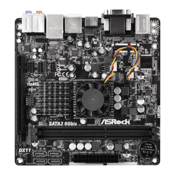
Page 9: Motherboard Layout
1.3 Motherboard Layout T48EM1 DDR3 CMOS CHA_FAN1 Battery USB 2.0 T: USB0 B: USB1 CLRCMOS1 USB 2.0 Super T: USB2 B: USB3 PANEL 1 CHA_FAN2 PLED PWRBTN HDLED RESET USB 2.0 Top: T: USB4 RJ-45 B: USB5 COM1 HD_AUDIO1 USB6_7... -
Page 10: I/O Panel
1.4 I/O Panel PS/2 Keyboard/Mouse Port (Purple/Green) Front Speaker (Lime)** D-Sub Port Microphone (Pink) USB 2.0 Ports (USB23) USB 2.0 Ports (USB45) LAN RJ-45 Port* eSATA3 Port Central / Bass (Orange) HDMI Port Rear Speaker (Black) DVI-D Port Optical SPDIF Out Port USB 2.0 Ports (USB01) Line In (Light Blue) * There are two LED next to the LAN port. - Page 11 To enable Multi-Streaming function, you need to connect a front panel audio cable to the front panel audio header. After restarting your computer, you will find “Mixer” tool on your system. Please select “Mixer ToolBox” , click “Enable playback multi-streaming”, and click “ok”.
-
Page 12: Installation
Chapter 2: Installation This is a Mini-ITX form factor motherboard. Before you install the motherboard, study the configuration of your chassis to ensure that the motherboard fits into it. Make sure to unplug the power cord before installing or removing the motherboard. -
Page 13: Installation Of Memory Modules (Dimm)
2.3 Installation of Memory Modules (DIMM) T48EM1 motherboard provides two 240-pin DDR3 (Double Data Rate 3) DIMM slots. It is not allowed to install a DDR or DDR2 memory module into DDR3 slot; otherwise, this motherboard and DIMM may be damaged. -
Page 14: Expansion Slot (Pci Express Slot)
2.4 Expansion Slot (PCI Express Slot) There is 1 PCI Express slot on this motherboard. PCIE slot: PCIE1 (PCIE x16 slot) is used for PCI Express x4 lane width graphics cards. Installing an expansion card Step 1. Before installing the expansion card, please make sure that the power supply is switched off or the power cord is unplugged. -
Page 15: Dual Monitor Feature
2.5 Dual Monitor Feature Dual Monitor Feature This motherboard supports dual monitor feature. With the internal graphics output support (DVI-D, D-Sub and HDMI), you can easily enjoy the benefits of dual monitor feature without installing any add-on graphics card to this motherboard. This motherboard also provides independent display controllers for DVI-D, D-Sub and HDMI to support dual graphics output so that DVI-D, D-sub and HDMI can drive same or different display contents. - Page 16 HDCP Function HDCP function is supported on this motherboard. To use HDCP function with this motherboard, you need to adopt the monitor that supports HDCP function as well. Therefore, you can enjoy the superior display quality with high-definition HDCP encryption contents. Please refer to below instruction for more details about HDCP function.
-
Page 17: Jumpers Setup
2.6 Jumpers Setup The illustration shows how jumpers are setup. When the jumper cap is placed on pins, the jumper is “Short”. If no jumper cap is placed on pins, the jumper is “Open”. The illustration shows a 3-pin jumper whose pin1 and pin2 are “Short”... -
Page 18: Onboard Headers And Connectors
2.7 Onboard Headers and Connectors Onboard headers and connectors are NOT jumpers. Do NOT place jumper caps over these headers and connectors. Placing jumper caps over the headers and connectors will cause permanent damage of the motherboard! Serial ATA3 Connectors These four Serial ATA3 (SATA3) connectors support SATA data (SATA3_1: see p.9, No. - Page 19 1. High Definition Audio supports Jack Sensing, but the panel wire on the chassis must support HDA to function correctly. Please follow the instruction in our manual and chassis manual to install your system. 2. If you use AC’97 audio panel, please install it to the front panel audio header as below: A.
- Page 20 The front panel design may differ by chassis. A front panel module mainly consists of power switch, reset switch, power LED, hard drive activity LED, speaker and etc. When connecting your chassis front panel module to this header, make sure the wire assignments and the pin assign-ments are matched correctly.
-
Page 21: Driver Installation Guide
2.8 Driver Installation Guide To install the drivers to your system, please insert the support CD to your optical drive first. Then, the drivers compatible to your system can be auto-detected and listed on the support CD driver page. Please follow the order from up to bottom side to install those required drivers. -
Page 22: Uefi Setup Utility
Chapter 3: UEFI SETUP UTILITY Introduction This section explains how to use the UEFI SETUP UTILITY to configure your system. The UEFI chip on the motherboard stores the UEFI SETUP UTILITY. You may run the UEFI SETUP UTILITY when you start up the computer. Please press <F2>... -
Page 23: Navigation Keys
3.1.2 Navigation Keys Please check the following table for the function description of each navigation key. Navigation Key(s) Function Description Moves cursor left or right to select Screens Moves cursor up or down to select items + / - To change option for the selected items <Enter>... -
Page 24: Oc Tweaker Screen
3.3 OC Tweaker Screen In the OC Tweaker screen, you can set up overclocking features. DRAM Timing Configuration DRAM Frequency If [Auto] is selected, the motherboard will detect the memory module(s) inserted and assigns appropriate frequency automatically. DRAM Timing Control Power Down Enable Use this item to enable or disable DDR power down mode. - Page 25 RAS# to CAS# Delay (tRCD) Use this item to change RAS# to CAS# Delay (tRCD) Auto/Manual setting. The default is [Auto]. Row Precharge Time (tRP) Use this item to change Row Precharge Time (tRP) Auto/Manual setting. The default is [Auto]. RAS# Active Time (tRAS) Use this item to change RAS# Active Time (tRAS) Auto/Manual setting.
- Page 26 +1.8V Voltage Use this to select +1.8V Voltage. Configuration options: [Auto], [1.85V] to [2.10V]. The default value is [Auto]. +1V Voltage Use this to select +1V Voltage. Configuration options: [Auto], [1.07V] to [1.16V]. The default value is [Auto]. User Default In this option, you are allowed to load and save three user defaults according to your own requirements.
-
Page 27: Advanced Screen
3.4 Advanced Screen In this section, you may set the configurations for the following items: CPU Configu- ration, North Bridge Configuration, South Bridge Configuration, Storage Configura- tion, Super IO Configuration, ACPI Configuration and USB Configuration. Setting wrong values in this section may cause the system to malfunction. -
Page 28: Cpu Configuration
3.4.1 CPU Configuration Cool ‘n’ Quiet Use this item to enable or disable AMD’s Cool ‘n’ Quiet technology. The default value is [Auto]. Configuration options: [Auto], [Enabled] and ® [Disabled]. If you install Windows 8.1 / 8 / 7 / XP and want to enable this function, please set this item to [Enabled]. -
Page 29: North Bridge Configuration
3.4.2 North Bridge Configuration Primary Graphics Adapter This item allows you to select the type of Primary VGA in case of multiple video controllers. The default value of this feature is [PCI Express]. Cofiguration options: [Onboard] and [PCI Express]. Share Memory This allows you to set onboard VGA share memory feature. -
Page 30: South Bridge Configuration
3.4.3 South Bridge Configuration Onboard HD Audio Select [Auto], [Enabled] or [Disabled] for the onboard HD Audio feature. Front Panel Select [Auto] or [Disabled] for the onboard HD Audio Front Panel. Onboard LAN This allows you to enable or disable the “Onboard LAN” feature. Restore on AC/Power Loss This allows you to set the power state after an unexpected AC/power loss. -
Page 31: Storage Configuration
3.4.4 Storage Configuration SATA Controller Use this to enable or disable SATA controller. The default value is [Enabled]. SATA Mode Use this to select SATA mode. Configuration options: [IDE Mode] and [AHCI Mode]. The default value is [IDE Mode]. 1. AHCI (Advanced Host Controller Interface) supports NCQ and other new features that will improve SATA disk performance but IDE mode does not have these advantages. -
Page 32: Super Io Configuration
3.4.5 Super IO Configuration Serial Port Use this item to enable or disable the onboard serial port. Serial Port Address Use this item to set the address for the onboard serial port. Configuration options: [Auto], [3F8 / IRQ4], [2F8 / IRQ3], [3E8 / IRQ4], [2E8 / IRQ3]. CIR Controller Use this item to enable or disable CIR controller. -
Page 33: Acpi Configuration
3.4.6 ACPI Configuration Suspend to RAM Use this item to select whether to auto-detect or disable the Suspend-to- RAM feature. Select [Auto] will enable this feature if the OS supports it. Check Ready Bit Use this item to enable or disable the feature Check Ready Bit. ACPI HPET Table Use this item to enable or disable ACPI HPET Table. - Page 34 Please disable CSM when you enable Fast Boot option. The default value is [Enabled].
-
Page 35: Usb Configuration
3.4.7 USB Configuration USB 2.0 Controller Use this item to enable or disable the use of USB 2.0 controller. Legacy USB Support Use this option to select legacy support for USB devices. There are four configuration options: [Enabled], [Auto], [Disabled] and [UEFI Setup Only]. The default value is [Enabled]. -
Page 36: Hardware Health Event Monitoring Screen
3.5 Hardware Health Event Monitoring Screen In this section, it allows you to monitor the status of the hardware on your system, including the parameters of the CPU temperature, motherboard temperature, CPU fan speed, chassis fan speed, and the critical voltage. CPU Fan Setting This allows you to set the CPU fan speed. -
Page 37: Boot Screen
3.6 Boot Screen In this section, it will display the available devices on your system for you to config- ure the boot settings and the boot priority. Fast Boot Fast Boot minimizes your computer’s boot time. There are three con- figuration options: [Disabled], [Fast] and [Ultra Fast]. - Page 38 Full Screen Logo Use this item to enable or disable OEM Logo. The default value is [En- abled]. AddOn ROM Display Use this option to adjust AddOn ROM Display. If you enable the option “Full Screen Logo” but you want to see the AddOn ROM information when the system boots, please select [Enabled].
-
Page 39: Security Screen
3.7 Security Screen In this section, you may set or change the supervisor/user password for the system. For the user password, you may also clear it. Secure Boot Use this to enable or disable Secure Boot. The default value is [Disabled]. -
Page 40: Exit Screen
3.8 Exit Screen Save Changes and Exit When you select this option, it will pop-out the following message, “Save configuration changes and exit setup?” Select [OK] to save the changes and exit the UEFI SETUP UTILITY. Discard Changes and Exit When you select this option, it will pop-out the following message, “Discard changes and exit setup?”... - Page 41 Click on a specific item then follow the installation wizard to install it. 4.2.4 Contact Information If you need to contact ASRock or want to know more about ASRock, welcome to visit ASRock’s website at http://www.asrock.com; or you may contact your dealer for further information.
- Page 42 Installing OS on a HDD Larger Than 2TB ® This motherboard is adopting UEFI BIOS that allows Windows OS to be installed on a large size HDD (>2TB). Please follow below procedure to install the operating system. ® 1. Please make sure to use Windows Vista 64-bit (with SP1 or above), ®...
Need help?
Do you have a question about the T48EM1 and is the answer not in the manual?
Questions and answers