ASROCK Z77 EXTREME6 User Manual
Hide thumbs
Also See for Z77 EXTREME6:
- Quick installation manual (256 pages) ,
- User manual (206 pages) ,
- Use and care manual (87 pages)

Related Manuals for ASROCK Z77 EXTREME6


Summary of Contents for ASROCK Z77 EXTREME6
-
Page 1: User Manual
Z77 Extreme6/TB4 User Manual Version 1.2 Published October 2012 Copyright©2012 ASRock INC. All rights reserved. -
Page 2: Copyright Notice
ASRock. ASRock assumes no responsibility for any errors or omissions that may appear in this manual. With respect to the contents of this manual, ASRock does not provide warranty of any kind, either expressed or implied, including but not limited to the implied warran- ties or conditions of merchantability or fitness for a particular purpose. -
Page 3: Table Of Contents
Operation Guide ........28 2.9 Thunderbolt ..............32 2.10 Dual Monitor and Surround Display Features ....33 2.11 ASRock Smart Remote Installation Guide ..... 36 2.12 Jumpers Setup ............... 38 2.13 Onboard Headers and Connectors ........ 39 2.14 Smart Switches .............. 45 2.15 Dr. - Page 4 3 UEFI SETUP UTILITY .......... 57 3.1 Introduction ..............57 3.1.1 UEFI Menu Bar ............ 57 3.1.2 Navigation Keys ........... 58 3.2 Main Screen ..............58 3.3 OC Tweaker Screen ............59 3.4 Advanced Screen ............64 3.4.1 CPU Configuration ..........65 3.4.2 North Bridge Configuration........
-
Page 5: Introduction
In case any modifications of this manual occur, the updated version will be available on ASRock website without further notice. You may find the latest VGA cards and CPU support lists on ASRock website as well. ASRock website http://www.asrock.com If you require technical support related to this motherboard, please visit our website for specific information about the model you are using. -
Page 6: Specifications
1.2 Specifications Platform - ATX Form Factor: 12.0-in x 9.6-in, 30.5 cm x 24.4 cm - Premium Gold Capacitor design (100% Japan-made high-quality Conductive Polymer Capacitors) ® - Supports 3 and 2 Generation Intel Core i7 / i5 / i3 in LGA1155 Package - Digi Power Design - 8 + 4 Power Phase Design... - Page 7 ports (see CAUTION 6) - Supports HDMI 1.4a Technology with max. resolution up to 1920x1200 @ 60Hz - Supports D-Sub with max. resolution up to 2048x1536 @ 75Hz - Supports Thunderbolt with max. resolution up to 2560x1600 @ 60Hz - Supports Auto Lip Sync, Deep Color (12bpc), xvYCC and HBR (High Bit Rate Audio) with HDMI (see CAUTION 7) - Supports HDCP function with HDMI - Supports Full HD 1080p Blu-ray (BD) / HD-DVD playback...
- Page 8 ® SATA3 - 2 x SATA3 6.0 Gb/s connectors by Intel Z77, support RAID (RAID 0, RAID 1, RAID 5, RAID 10, Intel Rapid Storage and Intel Smart Response Technology), NCQ, AHCI and Hot Plug - 2 x SATA3 6.0 Gb/s connectors by ASMedia ASM1061, support NCQ, AHCI and Hot Plug (SATA3_A2 connector is shared with the eSATA port) ®...
- Page 9 8 / 8 64-bit / 7 / 7 64-bit / Vista Vista 64-bit / XP / XP 64-bit compliant (see CAUTION 23) Certifications - FCC, CE, WHQL - ErP/EuP Ready (ErP/EuP ready power supply is required) (see CAUTION 24) * For detailed product information, please visit our website: http://www.asrock.com...
- Page 10 6-channel, and 8-channel modes. Please check the table on page 15 for proper connection. ASRock Extreme Tuning Utility (AXTU) is an all-in-one tool to ne-tune dif- ferent system functions in a user-friendly interface, which includes Hard- ware Monitor, Fan Control, Overclocking, OC DNA and IES. In Hardware Monitor, it shows the major readings of your system.
- Page 11 Please visit our website for the operation procedures of ASRock Extreme Tuning Utility (AXTU). ASRock website: http://www.asrock.com 10. ASRock Instant Flash is a BIOS flash utility embedded in Flash ROM. This convenient BIOS update tool allows you to update system BIOS ®...
- Page 12 15. ASRock XFast RAM is a new function that is included into ASRock Ex- treme Tuning Utility (AXTU). It fully utilizes the memory space that cannot ®...
- Page 13 ® ® 64-bit. Intel Smart Connect Technology and Intel USB 3.0 ports are not ® ® supported by Microsoft Windows Vista / Vista 64-bit / XP / XP 64- bit. 24. EuP stands for Energy Using Product, was a provision regulated by the European Union to define the power consumption for the completed system.
-
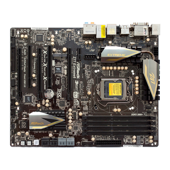
Page 14: Motherboard Layout
T: USB0 B: USB1 USB 3.0 Top: T: USB2 RJ-45 B: USB3 PWR_FAN1 CHA_FAN2 64Mb SLI/XFIRE_PWR1 CMOS BIOS PCIE1 Battery Z77 Extreme6/TB4 PCIE2 PCIE3 Intel PCI Express 3.0 PCI1 Fast LAN Fast USB Fast RAM RSTBTN PCIE4 AUDIO CODEC RoHS PWRBTN... -
Page 15: I/O Panel
1.4 I/O Panel PS/2 Keyboard/Mouse Port (Purple/Green) Optical SPDIF Out Port DisplayPort Input (HDMI_DP_1) Thunderbolt Port (TBT1) USB 2.0 Ports (USB01) Thunderbolt Port (TBT2) ** 4 LAN RJ-45 Port USB 3.0 Ports (USB3_23) D-Sub Port (VGA1) IEEE 1394 Port (1394) Central / Bass (Orange) **** 16 eSATA3 Connector... - Page 16 If you use 2-channel speaker, please connect the speaker’s plug into “Front Speaker Jack”. See the table below for connection details in accordance with the type of speaker you use. TABLE for Audio Output Connection Audio Output Channels Front Speaker Rear Speaker Central / Bass Line in (No.
-
Page 17: Installation
Chapter 2: Installation This is an ATX form factor (12.0" x 9.6", 30.5 x 24.4 cm) motherboard. Before you install the motherboard, study the configuration of your chassis to ensure that the motherboard fits into it. 2.1 Pre-installation Precautions Take note of the following precautions before you install motherboard components or change any motherboard settings. -
Page 18: Cpu Installation
2.3 CPU Installation In order to provide the LGA 1155 CPU sock- ets more protection and make the instal- lation process easier, ASRock has added a new protection cover on top of the load plate to replace the former PnP caps that were under the load plate. - Page 19 orientation key notch alignment key Pin1 Pin1 alignment key 1155-Pin Socket orientation key notch 1155-Pin CPU For proper installation, please ensure to match the two orientation key notches of the CPU with the two alignment keys of the socket. Step 2-3. Carefully place the CPU into the socket.
-
Page 20: Installation Of Cpu Fan And Heatsink
2.4 Installation of CPU Fan and Heatsink This motherboard is equipped with 1155-Pin socket that supports Intel 1155-Pin CPUs. Please adopt the type of heatsink and cooling fan compliant with Intel 1155- Pin CPU to dissipate heat. Before you install the heatsink, you need to spray ther- mal interface material between the CPU and the heatsink to improve heat dissipa- tion. -
Page 21: Installation Of Memory Modules (Dimm)
2.5 Installation of Memory Modules (DIMM) This motherboard provides four 240-pin DDR3 (Double Data Rate 3) DIMM slots, and supports Dual Channel Memory Technology. For dual channel config- uration, you always need to install identical (the same brand, speed, size and chip-type) DDR3 DIMM pair in the slots: You have to install identical DDR3 DIMMs in Dual Channel A (DDR3_A1 and DDR3_B1;... -
Page 22: Installing A Dimm
Installing a DIMM Please make sure to disconnect power supply before adding or removing DIMMs or the system components. Step 1. Unlock a DIMM slot by pressing the retaining clips outward. Step 2. Align a DIMM on the slot such that the notch on the DIMM matches the break on the slot. -
Page 23: Expansion Slots (Pci And Pci Express Slots)
PCIE slots: PCIE1 and PCIE3 (PCIE 2.0 x1 slots) are used for PCI Express x1 lane width cards, such as a Gigabit LAN card, SATA2 card or ASRock Game Blaster, etc. PCIE2 (PCIE 3.0 x16 slot) is used for PCI Express x16 lane width... -
Page 24: Sli Tm And Quad Sli Tm Operation Guide
2.7 SLI and Quad SLI Operation Guide ® This motherboard supports NVIDIA and Quad SLI (Scalable Link Interface) technology that allows you to install up to two identical PCI Express x16 graphics ® ® ® cards. Currently, NVIDIA technology supports all Windows OS. - Page 25 Step3. Align and insert the ASRock SLI_Bridge_2S Card to the goldfingers on each graphics card. Make sure the ASRock SLI_Bridge_2S Card is firmly in place. ASRock SLI_Bridge_2S Card Step4. Connect a VGA cable or a DVI cable to the monitor connector or the DVI...
-
Page 26: Driver Installation And Setup
2.7.2 Driver Installation and Setup Install the graphics card drivers to your system. After that, you can enable the Multi- ® Graphics Processing Unit (GPU) feature in the NVIDIA nView system tray utility. Please follow the below procedures to enable the multi-GPU feature. ®... - Page 27 ® For Windows Vista / Vista 64-bit / 7 / 7 64-bit / 8 / 8 64 bit OS: (For SLI and Quad SLI mode) A. Click the Start icon on your Windows taskbar. B. From the pop-up menu, select All Programs, and then click NVIDIA Corporation.
-
Page 28: Crossfirex Tm Tm
2.8 CrossFireX and Quad CrossFireX Operation Guide This motherboard supports CrossFireX and Quad CrossFireX . CrossFireX technology offers the most advantageous means available of combining multiple high performance Graphics Processing Units (GPU) in a single PC. Combining a range of different operating modes with intelligent software design and an innovative interconnect mechanism, CrossFireX enables the highest possible level of performance and image quality in any 3D application. - Page 29 Step 2. Connect two Radeon graphics cards by installing a CrossFire Bridge on the CrossFire Bridge Interconnects on the top of the Radeon graphics cards. (The CrossFire Bridge is provided with the graphics card you pur- chase, not bundled with this motherboard. Please refer to your graphics card vendor for details.) CrossFire Bridge Step 3.
- Page 30 2.8.2 Driver Installation and Setup Step 1. Power on your computer and boot into OS. Step 2. Remove the AMD drivers if you have any VGA drivers installed in your system. The Catalyst Uninstaller is an optional download. We recommend using this utility to uninstall any previously installed Catalyst drivers prior to installation.
- Page 31 Although you have selected the option “Enable CrossFire ”, the CrossFireX function may not work actually. Your computer will automatically reboot. After restarting your computer, please confirm whether the option “Enable CrossFire ” in “AMD Catalyst Control Center” is selected or not; if not, please select it again, and then you are able to enjoy the benefits of CrossFireX Step 7.
-
Page 32: Thunderbolt
2.9 Thunderbolt This motherboard has two thunderbolt connectors that support video output from internal VGA cards. Due to 32-bit OS limitations, we strongly recommend using a 64-bit OS to bring ThunderBolt into full play. For thunderbolt display installation please follow the steps below: Thunderbolt cables are provided by your monitor supplier. -
Page 33: Dual Monitor And Surround Display Features
2.10 Dual Monitor and Surround Display Dual Monitor This motherboard supports dual monitor. With the internal VGA output support (D-Sub HDMI and Thunderbolt), you can easily enjoy the benefits of dual monitor without in- stalling any add-on VGA cards to this motherboard. This motherboard also provides independent display controllers for D-Sub, HDMI and Thunderbolt to support dual VGA output so that the D-Sub, HDMI and Thunderbolt can drive the same or differ- ent display contents. - Page 34 Surround Display Feature This motherboard supports surround display upgrade. With the internal VGA output support (D-Sub HDMI and Thunderbolt) and external add-on PCI Express VGA cards, you can easily enjoy the benefits of surround display. Please refer to the following steps to set up a surround display environment: 1.
- Page 35 ® For Windows 8 / 8 64-bit / 7 / 7 64-bit / Vista / Vista 64-bit OS: Right click the desktop, choose “Personalize”, and select the “Display Settings” tab so that you can adjust the parameters of the multi-monitors according to the steps below.
-
Page 36: Asrock Smart Remote Installation Guide
2.11 ASRock Smart Remote Installation Guide ASRock Smart Remote is only used for ASRock motherboards with a CIR header. Please refer to the procedures below for the quick installation and usage of ASRock Smart Remote. Step1. Find the CIR header located next to the USB 2.0 header on your... - Page 37 The Multi-Angle CIR Receiver does not support Hot-Plug. Please install it before you boot the system. * ASRock Smart Remote is only supported by some ASRock motherboards. Please refer to ASRock's website for the motherboard support list: http://www.asrock.com...
-
Page 38: Jumpers Setup
2.12 Jumpers Setup The illustration shows how jumpers are setup. When the jumper cap is placed on pins, the jumper is “Short”. If no jumper cap is placed on pins, the jumper is “Open”. The illustration shows a 3-pin jumper whose pin1 and pin2 are “Short”... -
Page 39: Onboard Headers And Connectors
2.13 Onboard Headers and Connectors Onboard headers and connectors are NOT jumpers. Do NOT place jumper caps over these headers and connectors. Placing jumper caps over the headers and connectors will cause permanent damage of the motherboard! Serial ATA2 Connectors These four Serial ATA2 (SATA2) connectors support SATA data (SATA2_2_3: see p.14, No. - Page 40 (9-pin USB4_5) (see p.14, No. 26) (9-pin USB6_7) (see p.14, No. 27) USB 3.0 Header Besides four default USB 3.0 ports on the I/O panel, there is (19-pin USB3_4_5) one USB 3.0 header on this (see p.14, No. 8) motherboard. This USB 3.0 header can support two USB 3.0 ports.
- Page 41 1. High Definition Audio supports Jack Sensing, but the panel wire on the chassis must support HDA to function correctly. Please follow the instruction in our manual and chassis manual to install your system. 2. If you use AC’97 audio panel, please install it to the front panel audio header as below: A.
- Page 42 The front panel design may differ by chassis. A front panel module mainly consists of power switch, reset switch, power LED, hard drive activity LED, speaker and etc. When connecting your chassis front panel module to this header, make sure the wire assignments and the pin assign-ments are matched correctly.
- Page 43 Though this motherboard provides 4-Pin CPU fan (Quiet Fan) support, the 3-Pin CPU fan still can work successfully even without the fan speed control function. If you plan to connect the 3-Pin CPU fan to the CPU fan connector on this motherboard, please connect it to Pin 1-3.
- Page 44 SLI/XFIRE Power Connector It is not necessary to use this connector, but please connect it (4-pin SLI/XFIRE_PWR1) with a hard disk power (see p.14 No. 40) connecor when two graphics SLI/XFIRE_POWER1 cards are plugged to this motherboard. IEEE 1394 Header Besides one default IEEE 1394 port on the I/O panel, there is (9-pin FRONT_1394)
-
Page 45: Smart Switches
2.14 Smart Switches The motherboard has three smart switches: power switch, reset switch and clear CMOS switch, allowing users to quickly turn on/off or reset the system to clear the CMOS values. Power Switch Power Switch is a smart switch, allowing users to quickly turn (PWRBTN) on/off the system. -
Page 46: Dr. Debug
2.15 Dr. Debug Dr. Debug is used to provide code information, which makes troubleshooting even easier. Please see the diagrams below for reading the Dr. Debug codes. Status Code Description 0x00 Not used 0x01 Power on. Reset type detection (soft/hard) 0x02 AP initialization before microcode loading 0x03... - Page 47 0x37 Post-Memory North Bridge initialization is started 0x38 Post-Memory North Bridge initialization (North Bridge module specific) 0x39 Post-Memory North Bridge initialization (North Bridge module specific) 0x3A Post-Memory North Bridge initialization (North Bridge module specific) 0x3B Post-Memory South Bridge initialization is started 0x3C Post-Memory South Bridge initialization (South Bridge module specific) 0x3D...
- Page 48 0x62 Installation of the South Bridge Runtime Services 0x63 CPU DXE initialization is started 0x64 CPU DXE initialization (CPU module specific) 0x65 CPU DXE initialization (CPU module specific) 0x66 CPU DXE initialization (CPU module specific) 0x67 CPU DXE initialization (CPU module specific) 0x68 PCI host bridge initialization 0x69...
- Page 49 0xA6 SCSI Detect 0xA7 SCSI Enable 0xA8 Setup Verifying Password 0xA9 Start of Setup 0xAA Reserved for ASL 0xAB Setup Input Wait 0xAC Reserved for ASL 0xAD Ready To Boot event 0xAE Legacy Boot event 0xAF Exit Boot Services event 0xB0 Runtime Set Virtual Address MAP Begin 0xB1...
-
Page 50: Serial Ata (Sata) / Serial Ata2 (Sata2) Hard Disks Installation
2.16 Serial ATA (SATA) / Serial ATA2 (SATA2) Hard Disks Installation ® This motherboard adopts Intel Z77 chipset that supports Serial ATA (SATA) / Serial ATA2 (SATA2) hard disks and RAID (RAID 0, RAID 1, RAID 5, RAID 10, Intel Rapid Storage and Intel Smart Response Technology) functions. -
Page 51: Hot Plug And Hot Swap For Sata / Sata2 Hdds
2.18 Hot Plug and Hot Swap for SATA / SATA2 HDDs This motherboard supports Hot Plug and Hot Swap for SATA / SATA2 in RAID ® / AHCI mode. Intel Z77 chipset provides hardware support for Advanced Host controller Interface (AHCI), a new programming interface for SATA host controllers developed through a joint industry effort. -
Page 52: Sata / Sata2 / Sata3 Hdd Hot Plug Operation Guide
3. Please make sure the SATA / SATA2 / SATA3 driver is installed into system properly. The latest SATA / SATA2 / SATA3 driver is available on our support website: www.asrock.com 4. Make sure to use the SATA power cable & data cable from our motherboard package. - Page 53 How to Hot Plug a SATA / SATA2 / SATA3 HDD: Points of attention, before you process Hot Plug: Please follow the instructions below to process Hot Plug. Improper procedures will cause the SATA / SATA2 / SATA3 HDD damage and data loss. Step 2 Step 1 Please connect the SATA power cable’s...
-
Page 54: Driver Installation Guide
2.21 Driver Installation Guide To install the drivers to your system, please insert the support CD to your optical drive first. Then, the drivers compatible to your system can be auto-detected and listed on the support CD driver page. Please follow the order from top to bottom to install those required drivers. -
Page 55: Installing Windows ® 8 / 8 64-Bit / 7 / 7 64-Bit / Vista
® 2.23 Installing Windows 8 / 8 64-bit / 7 / 7 64-bit / Vista Vista 64-bit / XP / XP 64-bit Without RAID ® If you want to install Windows 8 / 8 64-bit / 7 / 7 64-bit / Vista / Vista 64-bit / XP / XP 64-bit OS on your SATA / SATA2 / SATA3 HDDs without RAID functions, please... -
Page 56: Installing Windows ® 8 / 8 64-Bit / 7 / 7 64-Bit
® 2.23.2 Installing Windows 8 / 8 64-bit / 7 / 7 64-bit / Vista Vista 64-bit Without RAID ® If you want to install Windows 8 / 8 64-bit / 7 / 7 64-bit / Vista / Vista 64-bit OS on your SATA / SATA2 / SATA3 HDDs without RAID functions, please follow the steps below. -
Page 57: Uefi Setup Utility
Chapter 3: UEFI SETUP UTILITY 3.1 Introduction This section explains how to use the UEFI SETUP UTILITY to configure your sys- tem. The UEFI chip on the motherboard stores the UEFI SETUP UTILITY. You may run the UEFI SETUP UTILITY when you start up the computer. Please press <F2> or <Delete>... -
Page 58: Navigation Keys
3.1.2 Navigation Keys Please check the following table for the descriptions of each navigation key. Navigation Key(s) Function Description + / - To change option for the selected items <Tab> Switch to next function <PGUP> Go to the previous page <PGDN>... -
Page 59: Oc Tweaker Screen
3.3 OC Tweaker Screen In the OC Tweaker screen, you can set up overclocking features. No-K OC For those CPUs that aren’t K-series, No-K OC can unleash the CPU’s power by boosting its frequency with just one click. Load Optimized GPU OC Setting You can use this option to load optimized GPU overclocking settings. - Page 60 Please note that enabling this function may reduce CPU voltage and lead to system stability or compatibility issues with some power supplies. Please set this item to [Disabled] if above issues occur. Intel Turbo Boost Technology Use this item to enable or disable Intel Turbo Boost Mode Technology. Turbo Boost Mode allows processor cores to run faster than marked fre- quency in specific conditions.
- Page 61 DRAM Configuration DRAM tCL Use this item to change CAS# Latency (tCL) Auto/Manual setting. The default is [Auto]. DRAM tRCD Use this item to change RAS# to CAS# Delay (tRCD) Auto/Manual setting. The default is [Auto]. DRAM tRP Use this item to change Row Precharge Time (tRP) Auto/Manual setting. The default is [Auto].
- Page 62 DRAM tRTP Use this item to change Read to Precharge (tRTP) Auto/Manual setting. The default is [Auto]. DRAM tFAW Use this item to change Four Activate Window (tFAW) Auto/Manual set- ting. The default is [Auto]. DRAM tCWL Use this item to change CAS# Write Latency (tCWL) Auto/Manual setting. The default is [Auto].
- Page 63 CPU PLL Voltage Use this to select CPU PLL Voltage. The default value is [Auto]. VCCSA Voltage Use this to select VCCSA Voltage. The default value is [Auto]. User Defaults In this option, you are allowed to load and save three user defaults accord- ing to your own requirements.
-
Page 64: Advanced Screen
3.4 Advanced Screen In this section, you may set the configurations for the following items: CPU Configu- ration, North Bridge Configuration, South Bridge Configuration, Storage Configura- tion, Intel(R) Rapid Start Technology, Intel(R) Smart Connect Technology, Intel(R) Thunderbolt, Super IO Configuration, ACPI Configuration, USB Configuration and Network Configuration. -
Page 65: Cpu Configuration
3.4.1 CPU Configuration Intel Hyper Threading Technology To enable this feature, a computer system with an Intel processor that supports Hyper-Threading technology and an operating system that in- ® ® cludes optimization for this technology, such as Microsoft Windows XP / ®... - Page 66 No-Execution (NX) Memory Protection Technology is an enhancement to the IA-32 Intel Architecture. An IA-32 processor with “No Execute (NX) Memory Protection” can prevent data pages from being used by malicious software to execute codes. This option will be hidden if the current CPU does not support No-Excute Memory Protection.
-
Page 67: North Bridge Configuration
3.4.2 North Bridge Configuration Primary Graphics Adapter This allows you to select [Onboard], [PCI] or [PCI Express] as the boot graphic adapter priority. The default value is [PCI Express]. VT-d Use this item to enable/disable Intel(R) Virtualization Technology for Di- rected I/O. -
Page 68: South Bridge Configuration
3.4.3 South Bridge Configuration Onboard HD Audio Select [Auto], [Enabled] or [Disabled] for the onboard HD Audio feature. If you select [Auto], the onboard HD Audio will be disabled when PCI Sound Card is plugged. Front Panel Select [Auto] or [Disabled] for the onboard HD Audio Front Panel. Onboard HDMI HD Audio This allows you to enable or disable the Onboard HDMI HD Audio feature. -
Page 69: Storage Configuration
3.4.4 Storage Configuration SATA Controller(s) Use this item to enable or disable the SATA Controller feature. SATA Mode Selection This item is for SATA3_0, SATA3_1 and SATA2_2 to SATA2_5 ports. Use this to select SATA mode. Configuration options: [IDE Mode], [AHCI Mode] and [RAID Mode]. - Page 70 ® We recommend to use Intel Z77 SATA ports (SATA3_0, SATA3_1, SATA2_2, SATA2_3, SATA2_4 and SATA2_5) for your bootable devices. This will minimum your boot time and get the best performance. But if you still want to boot from ASMedia SATA3 controller, you can still enable this in UEFI.
-
Page 71: Intel(R) Rapid Start Technology
3.4.5 Intel(R) Rapid Start Technology Intel(R) Rapid Start Technology Use this item to enable or disable Intel(R) Rapid Start Technology. Intel(R) Rapid Start Technology is a new zero power hibernation mode which al- lows users to resume in just 5-6 seconds. The default is [Enabled]. Entry After Select a time to enable RTC wake timer at S3 entry. -
Page 72: Intel(R) Smart Connect Technology
3.4.6 Intel(R) Smart Connect Technology Intel(R) Smart Connect Technology Use this item to enable or disable Intel(R) Smart Connect Technology. Intel(R) Smart Connect Technology keeps your e-mail and social networks, such as Twitter, Facebook, etc. updated automatically while the computer is in sleep mode. -
Page 73: Intel(R) Thunderbolt
3.4.7 Intel(R) Thunderbolt Wake From Thunderbolt Devices This allows you to enable or disable system wake from Thunderbolt de- vices. Security Level Use this to select the level of security. Thunderbolt Wake Delay Use this to configure Thunderbolt Wake Delay. Thunderbolt Extra Bus Reserved Use this to configure Thunderbolt Extra Bus Reserved. -
Page 74: Super Io Configuration
3.4.8 Super IO Configuration Serial Port Use this item to enable or disable the onboard serial port. Serial Port Address Use this item to set the address for the onboard serial port. Configuration options: [3F8h / IRQ4] and [3E8h / IRQ4]. Infrared Port Use this item to enable or disable the onboard infrared port. -
Page 75: Acpi Configuration
3.4.9 ACPI Configuration Suspend to RAM Use this item to select whether to auto-detect or disable the Suspend-to- RAM feature. Selecting [Auto] will enable this feature if the OS supports it. Check Ready Bit Use this item to enable or disable the feature Check Ready Bit. ACPI HPET Table Use this item to enable or disable ACPI HPET Table. -
Page 76: Usb Configuration
3.4.10 USB Configuration USB 2.0 Controller Use this item to enable or disable the use of USB 2.0 controller. USB 3.0 Controller Use this item to enable or disable the use of USB 3.0 controller. Legacy USB Support Use this option to select legacy support for USB devices. There are four configuration options: [Enabled], [Auto], [Disabled] and [UEFI Setup Only]. -
Page 77: Network Configuration
3.4.11 Network Configuration Internet Setting Use this item to configure internet settings for Internet Flash. UEFI Download Server Use this item to select a server for Internet Flash to download the latest UEFI. -
Page 78: Hardware Health Event Monitoring Screen
3.5 Hardware Health Event Monitoring Screen In this section, it allows you to monitor the status of the hardware on your system, including the parameters of the CPU temperature, motherboard temperature, CPU fan speed, chassis fan speed, and the critical voltage. CPU Fan 1 &... - Page 79 before it returns to S4/S5 state. Dehumidifier CPU Fan Setting Use this setting to configure CPU fan speed while “Dehumidifier” is en- abled.
-
Page 80: Boot Screen
3.6 Boot Screen In this section, it will display the available devices on your system for you to config- ure the boot settings and the boot priority. Fast Boot Fast Boot minimizes your computer’s boot time. Configuration options: [Disabled] - Disable Fast Boot. [Fast]: When selecting “Fast”, it is not allowed to boot from a USB storage device. - Page 81 AddOn ROM Display Use this option to adjust AddOn ROM Display. If you enable the option “Full Screen Logo” but you want to see the AddOn ROM information when the system boots, please select [Enabled]. Configuration options: [Enabled] and [Disabled]. The default value is [Enabled]. Boot Failure Guard Enable or disable the feature of Boot Failure Guard.
-
Page 82: Security Screen
3.7 Security Screen In this section, you may set or change the supervisor/user password for the system. For the user password, you may also clear it. -
Page 83: Exit Screen
3.8 Exit Screen Save Changes and Exit When you select this option, the following message “Save configuration changes and exit setup?” will pop-out. Select [Yes] to save the changes and exit the UEFI SETUP UTILITY. Discard Changes and Exit When you select this option, the following message “Discard changes and exit setup?”... -
Page 84: Software Support
Click on a specific item then follow the installation wizard to install it. 4.2.4 Contact Information If you need to contact ASRock or want to know more about ASRock, welcome to visit ASRock’s website at http://www.asrock.com; or you may contact your... - Page 85 Installing OS on a HDD Larger Than 2TB in AHCI Mode ® This motherboard adopts UEFI BIOS that allows Windows OS to be installed on a large size HDD (>2TB). Please follow the procedures below to install the operating system. ®...
- Page 86 RAID drivers into a USB flash disk. You can download the driver from ASRock's website and unzip the file into a USB flash disk OR copy the file from ASRock motherboard support CD. (please copy the files under the following directory: 32 bit: ..\i386\Win7_Vista_Intel..
- Page 87 E. Please keep the USB flash disk installed until the system's first reboot. ® F. Continue to install OS by following the Windows instructions. ® 5. Follow Windows Installation Guide to install OS. ® If you install Windows 8 64-bit / 7 64-bit / Vista 64-bit on a large hard disk ®...
- Page 88 B. Disable “Volume Shadow Copy” service. a. Type “computer management” in the Start Menu, then press “Enter”. b. Go to “Services and Applications>Services”; Then double click “Volume Shadow Copy”.
- Page 89 c. Set “Startup type” to “Disable” then Click “OK”. C. Reboot your system. D. After reboot, please start to install motherboard drivers and utilities. ® Windows 7 64-bit: A. Please request the hotfix KB2505454 through this link: http://support.microsoft.com/kb/2505454/ ® B. After installing Windows 7 64-bit, install the hotfix kb2505454.
Need help?
Do you have a question about the Z77 EXTREME6 and is the answer not in the manual?
Questions and answers