
Subscribe to Our Youtube Channel
Related Manuals for Icom IC-iF9511HT


Summary of Contents for Icom IC-iF9511HT
- Page 1 INSTRUCTION MANUAL VHF P25 TRUNKING MOBILE TRANSCEIVER iF9511HT This device complies with Part 15 of the FCC Rules. Op- eration is subject to the condition that this device does not cause harmful interference.
-
Page 2: Explicit Definitions
See the operating guide for details of Analog and APCO cryption of this product is activated, you must comply with the P25 system operations. Consult your Icom dealer or sys- export regulations of your country, which can be highly restric- tem operator for details concerning your transceivers pro- tive. -
Page 3: Fcc Information
FCC INFORMATION ABOUT IPR • FOR CLASS B UNINTENTIONAL RADIATORS: This device is made under license under one or more of the following U.S. Patents: #4,590,473; #4,636,791; #5,148,482; This equipment has been tested and found to comply with the #5,185,796; #5,271,017; #5,377,229; #4,716,407; #4,972,460; limits for a Class B digital device, pursuant to part 15 of the #5,502,767;... -
Page 4: Precautions
CAUTION: Changes or modifications to this transceiver, not in areas subject to direct sunlight, such as the dashboard. expressly approved by Icom Inc., could void your authority to DO NOT place the transceiver in excessively dusty envi- operate this transceiver under FCC regulations. -
Page 5: Table Of Contents
TABLE OF CONTENTS IMPORTANT ................i 3 CONNECTION AND MAINTENANCE ....14−21 EXPLICIT DEFINITIONS ............i n Separation cable connection ........14 FCC INFORMATION ............ii n Rear panel connection ..........16 ABOUT IPR ................ii n Supplied Accessories ..........17 VOICE CODING TECHNOLOGY ......... ii n Mounting the transceiver ..........18 PRECAUTIONS .............. -
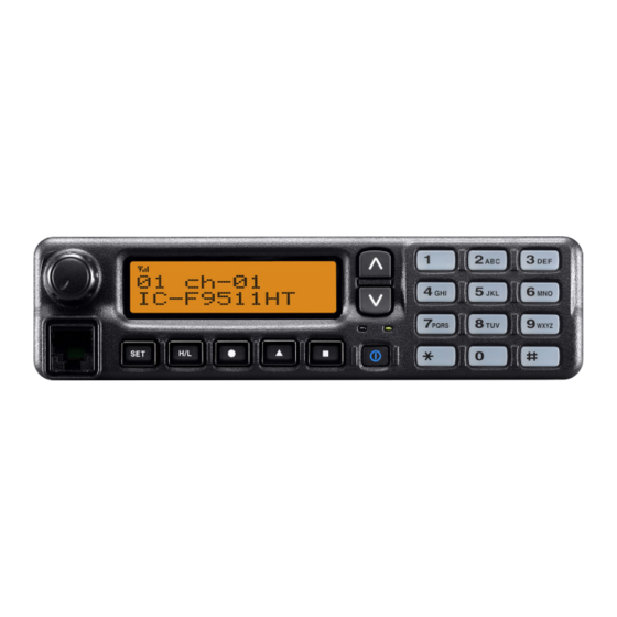
Page 6: Panel Description
PANEL DESCRIPTION n Front panel— Controller c h - 0 1 I C - F 9 5 1 1 H T q AF VOLUME CONTROL KNOB r 10-KEYPAD Rotate the knob to adjust the audio output level. The keypad allows you to enter digits to: •... - Page 7 PANEL DESCRIPTION y POWER SWITCH [POWER] NEVER connect non-specified microphones. The pin Push to turn the power ON and OFF. assignments may be different and the transceiver may • The following functions are available at power ON as options: be damaged. - Automatic scan start - Password prompt D MICROPHONE...
-
Page 8: Function Display- Controller
COMPANDER INDICATOR Trunking/Conventional system operations. Consult your Appears when the compander function is activated. Icom dealer or system operator for details concerning * Analog mode operation only your transceiver’s programming. t SCRAMBLER INDICATOR Appears when the voice scrambler or encryption function... -
Page 9: Programmable Function Keys
➥ Push to start and cancel scanning operation. • When Power ON Scan function is activated, push to pause the Consult your Icom dealer or system operator for details con- scanning operation. And the paused scan resumes after the cerning your transceivers programming. - Page 10 PANEL DESCRIPTION PRIO A/B KEYS RX SPEAKER KEY ➥ Push to select Priority A or Priority B channel. Push to turn the RX speaker function ON or OFF. ➥ Push and hold [Prio A (Rewrite)] or [Prio B (Rewrite)] for When the RX speaker function is turned ON, the received 1 sec.
- Page 11 PANEL DESCRIPTION SURVEILLANCE KEY CLOCK KEY Push to turn the surveillance function ON or OFF. ➥ Push to indicate the current time on the LCD. (p. 9) When this function is turned ON, the beep is not emitted and • While the current time is indicated, push and hold this key for 1 sec.
-
Page 12: Basic Operation
BASIC OPERATION n Turning power ON n Channel selection When you use the transceiver for the first time, or after the Several types of channel selections are available. Methods transceiver has been left unused for a long time, make may differ according to your system set up. sure to check the date and time indication after turning the NON-ZONE TYPE: power ON. -
Page 13: Receiving And Transmitting
BASIC OPERATION n Receiving and transmitting D Transmitting notes Receiving: • Transmit inhibit function q Push [ ] to turn the power ON. The transceiver has several inhibit functions which restrict w Push [CH Up] or [CH Down] to select a channel in se- transmission under the following conditions: quence. -
Page 14: Clock Function
BASIC OPERATION n Clock function D Time and date settings The transceiver indicates the current time and date when [Clock] is pushed. And you can change the indication format q Push [Clock] to indicate the current time and date on the and time/date settings. -
Page 15: Wake Up Function
BASIC OPERATION n Wake up function The wake up function allows the transceiver to be automati- t Push [Clock] to set. cally turned ON according to the wake up time setting. • The next item blinks. q Push and hold [Clock] for 1 sec. to enter the clock set mode. -
Page 16: Sleep Function
BASIC OPERATION n Sleep function t Push [CH Up] or [CH Down] to input the ‘hour’ data for The sleep function allows the transceiver to be automatically wake up time. After inputting, push [Clock] to set. turned OFF according to the sleep time setting. •... -
Page 17: User Set Mode
BASIC OPERATION n User set mode y Push [CH Up] or [CH Down] to input the ‘hour’ data for The user set mode is accessed with [User Set Mode] and sleep time. After inputting, push [Clock] to set. allows you to set seldom-changed settings. In this case you •... - Page 18 BASIC OPERATION e Push [P0] several times to select the appropriate item. Then, push [Up] or [Down] to set the desired level/condi- tion. • Available set mode functions are Backlight, LCD Contrast, Beep, Beep Level, Ringer Level, SQL Level, AF Min. Level, Mic Gain, Horn, Battery Voltage, Signal Moni and System In- formation.
-
Page 19: Connection And Maintenance
• The cable can be inserted into either the left or right grooves as the separation cable. desired. Rear plate NOTE: The following connections should be performed by your Icom dealer or distributor. The supplied or optional separation cable is required for the Screw the removed Separation circuit board screw controller and the main unit connection. - Page 20 CONNECTION AND MAINTENANCE D Main unit q Unscrew the 4 screws of the front plate (either the left or w Connect the opposite side of the separation cable that is right), then remove the front plate from the main unit. connected to the controller described on the previous page as shown below.
-
Page 21: Rear Panel Connection
Connect an Contact your dealer about an- external unit. performed by your Icom tenna selection and placement. dealer or distributor. R CAUTION! NEVER remove t h e f u s e - h o l d e r s f r o m t h e black and red cables. -
Page 22: Supplied Accessories
CONNECTION AND MAINTENANCE n Supplied Accessories Microphone Microphone hanger Mounting bracket and screw set Flat washers Mounting screws for main unit (M5) (M5×12) Spring washers Self-tapping screws (M5×16) (M5) Black and red cables DC power cable with fuse holders Nuts (M5) Bracket bolts Socket terminals Crimp terminals... -
Page 23: Mounting The Transceiver
CONNECTION AND MAINTENANCE n Mounting the transceiver D Main unit • Function name stickers There are no names on the programmable function keys The universal mounting bracket supplied with your transceiver since the functions can be freely assigned to these keys. allows overhead mounting. - Page 24 CONNECTION AND MAINTENANCE D Controller Overhead mounting 2 types of mounting styles are available— one is overhead mounting, and other one is on-board mounting. • Mount the controller securely with the 4 supplied screws to a thick surface which can support more than 2 kg (4.40 lb). On-board mounting (Overhead mounting) Flat washer...
-
Page 25: Antenna
CONNECTION AND MAINTENANCE n Antenna n Cleaning A key element in the performance of any communication sys- If the transceiver becomes dusty or dirty, wipe it clean with a tem is an antenna. Contact your dealer about antennas and soft, dry cloth. the best places to mount them. -
Page 26: Speaker Connector Information
CONNECTION AND MAINTENANCE n Speaker connector information q w e r t y u i o Connector’s front view Pin No. Name Description Specifications IGSW cont. In 0 − Vcc Output power : Max. 20 W RXSP1 RX AF Out (BTL) Impedance : 4 ø... -
Page 27: Options
OPTIONS • OPC-607/OPC-608/OPC-609/OPC-726 Icom optional equipment is designed for optimal perfor- mance when used with this transceiver. We are not respon- separation cables Used for a controller and a main unit connection. sible for the transceiver being damaged or any accident OPC-607 : 3 m;... -
Page 28: Safety Training Information
Electromagnetic Interference/Compatibility 48 centimeters separation distance. In order to ensure this distance During transmissions, your Icom radio generates RF energy that can is met, the installation of the antenna must be mounted at least 48 possibly cause interference with other devices or systems. To avoid... - Page 29 MEMO...
- Page 30 MEMO...
- Page 31 MEMO...
- Page 32 A-6718D-1US Printed in Japan © 2008 Icom Inc. 1-1-32 Kamiminami, Hirano-ku, Osaka 547-0003, Japan Printed on recycled paper with soy ink.
Need help?
Do you have a question about the IC-iF9511HT and is the answer not in the manual?
Questions and answers