
Subscribe to Our Youtube Channel
Related Manuals for LAPP ETHERLINE ACCESS U04TP01T

Summary of Contents for LAPP ETHERLINE ACCESS U04TP01T
- Page 1 ETHERLINE ACCESS SWITCH Hardware Installation Manual ETHERLINE ACCESS U04TP01T V1.0, December 2019 For more information please visit: https://www.lappkabel.com/activenetworkcomponents...
- Page 2 ETHERLINE ACCESS U04TP01T Hardware Installation Manual Disclaimer: U.I. Lapp GmbH tries to keep the content of this manual as accurate and as updated as possible. This document is not guaranteed to be error-free, and we reserve the right to amend it without notice to users.
- Page 3 Please keep the manual for further reference. If the equipment is used in a manner not specified in this manual, the protection provided by the equipment may be impaired. LAPP is not liable to any personal or equipment damage caused by violation of this notice.
- Page 4 Dispose of the device in accordance with relevant national provisions, preventing environmental pollution. In the following cases, please immediately shut down your power supply and contact your LAPP representative: Water gets into the equipment. Equipment damage or shell damage.
-
Page 5: Table Of Contents
Contents 1 Product Overview .......................1 2 Structure and Interface .......................2 2.1 Front Panel ........................2 2.2 Top Panel ........................3 3 Mounting ..........................3 3.1 Dimension Drawing ......................3 3.2 Mounting ........................4 3.2.1 DIN-Rail Mounting ....................4 3.2.2 DIN-Rail Dismounting ....................5 4 Connection .........................6 4.1 10/100Base-T(X) Ethernet Port ..................6 4.2 Grounding ........................8 4.3 Power Terminal Block ....................8 4.4 DIP Switches ........................9... -
Page 6: Product Overview
30 watts to PoE terminals directly, eliminating the need of additional wiring. The ETHERLINE ACCESS U04TP01T supports wide operating temperature range of -40℃ to 75℃, IP30 rated metal housing and 24VDC dual power inputs, becoming an economical and harsh-environment-resistant solution for the ITS, video surveillance and other automation applications. -
Page 7: Structure And Interface
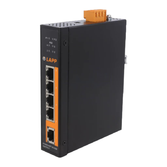
2 Structure and Interface 2.1 Front Panel Figure 1 Front Panel (1) Power 1 LED (2) Power 2 LED (3) POE LED (4) Link/ACT LED of 10/100Base-T(X) PoE Ethernet port (green) (5) Speed LED of 10/100Base-T(X) PoE Ethernet port (yellow) (6) Link/ACT LED of 10/100Base-T(X) Ethernet port (green) (7) Speed LED of 10/100Base-T(X) Ethernet port (yellow) (8) 10/100Base-T(X) PoE Ethernet port... -
Page 8: Top Panel
2.2 Top Panel Figure 2 Top Panel 3 Mounting 3.1 Dimension Drawing Figure 3 ETHERLINE ACCESS U04TP01T Dimensions (unit: mm) -
Page 9: Mounting
Caution: As part of the heat dissipation system, the housing of the switch becomes hot while working. Please do not touch or cover the housing while the switch is working. 3.2 Mounting The device supports DIN-rail mounting. Mounting Environment: 1) The temperature, humidity and power supply is within the allowable range. 2) No direct sunlight, distant from heat source and areas without strong electromagnetic interference. -
Page 10: Din-Rail Dismounting
Figure 4 DIN-Rail Mounting 3.2.2 DIN-Rail Dismounting Step 1: As shown in the following figure, press the device downward and move the device in direction 1 until the bottom of the device is detached from the DIN rail. Step 2: Pull the device upward and move the device in direction 2 until the device is removed from the DIN rail completely. -
Page 11: Connection
4 Connection 4.1 10/100Base-T(X) Ethernet Port Data Transmission 10/100Base-T(X) Ethernet port is equipped with RJ45 connector. The port is self-adaptive. It can automatically configure itself to work in 10M or 100M state, full or half duplex mode. The port can also adapt to MDI or MDI-X connection automatically. You can connect the port to a terminal or network device with a straight-through or cross-over cable. - Page 12 Table 2 Pin Definitions of POE Power Supply Power Wiring Sequence Figure 7 Connection Using Straight-through/Cross-over Cable Note: The color of the cable for RJ45 connector meets the 568B standard: 1-orange and white, 2- orange, 3-green and white, 4-blue, 5-blue and white, 6-green, 7-brown and white, and 8-brown.
-
Page 13: Grounding
4.2 Grounding Grounding protects the device from lightning and interference. Therefore, you must ground the device properly. You need to ground the switch before it is powered on and disconnect the grounding cable after the device is powered off. There is a grounding screw (see Figure 2) on the top panel for chassis grounding. After crimping one end of the grounding cable to a cold pressed terminal, secure the end of the grounding cable to the grounding screw and firmly connect the other end to ground. -
Page 14: Dip Switches
Wiring and Mounting Step 1: Ground the device properly according to section 4.2. Step 2: Remove the power terminal block from the device. Step 3: Insert the power wires into the power terminal block according to Table 3 and tighten the wires. -
Page 15: Leds
Table 5 Description of the DIP Switches DIP Switches State Description Enable broadcast storm protection Ⅰ Disable broadcast storm protection Transmit Jumbo frame (up to 10KB) Ⅱ Drop Jumbo frame 5 LEDs Table 6 LEDs State Description Power 1 is connected and operates properly. P1 LED Power 1 is not connected or operates abnormally. -
Page 16: Basic Features And Specifications
Rated Power Consumption Max 60W PoE output@12VDC, Max 6A and Input Current Max 120W PoE output@24VDC, Max 6A Data Port Model 10/100Base-T(X) RJ45 Port 10/100Base-T(X) RJ45 POE Port ETHERLINE ACCESS U04TP01T Physical Characteristics Housing Metal, fanless Protection Class IP30 Installation DIN-Rail Mounting 30mm×134mm×106mm...
Need help?
Do you have a question about the ETHERLINE ACCESS U04TP01T and is the answer not in the manual?
Questions and answers