Table of Contents
Advertisement
Quick Links
Advertisement
Table of Contents

Related Manuals for CAL Controls CAL 9500P


Summary of Contents for CAL Controls CAL 9500P
- Page 1 Users Manual CAL 9500P Programmable Process Controller CAL Controls...
-
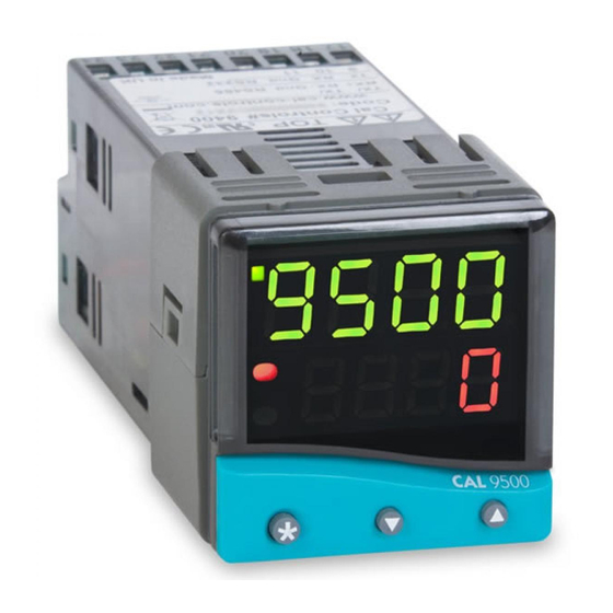
Page 2: Instrument Panel Features
INDEX INSTRUMENT PANEL FEATURES This page can be photocopied and used as a visual aid and bookmark when working in other parts of the manual. INSTRUMENT PANEL FEATURES Green LED: FUNCTIONS MENU GETTING STARTED Setpoint 1 output indicator Right Red LED: Initial Set-up AUTOTUNE Program Holdback... -
Page 3: Functions Menu
FUNCTIONS This page can be photocopied and used as a visual aid and bookmark when MENU working in other parts of the manual. LEVL 4 DER.S DI.SS NO.AL PROG LOCK SET.L USER- PROT E CT E D S E T T I NG S LEVL 3 SP1.D SP2.D BURN REU.D REU.L SPAN ZERO CHEK READ TECH UER RSET... -
Page 4: Getting Started
GETTING STARTED Press and hold and use the buttons to select from the choices Rly , SSd or AnLG depending on the model supplied. SP2 and SP3 outputs will be automatically After power-up the controller requires programming with the following information: allocated. -
Page 5: Proportional Cycle-Time
AUTOTUNE (continued) SECOND AND THIRD SETPOINTS (SP2 and SP3) PRIMARY ALARM MODES Hereafter in the Manual the symbol ( ) signifies both buttons are held pressed for 3 seconds to ENTER or EXIT Program mode. Configure SP2 output to operate as an alarm from SP2.A in Level 2 and set the alarm setting in SEt.2 Level 1. -
Page 6: Linear Input
LINEAR INPUT SP2 / SP3 OUTPUT AND LED STATUS IN ALARM CONDITION SP2 / SP3 ALARM ANNUNCIATOR Set-up Procedure If a Primary Alarm mode has been configured, when an alarm condition occurs the alarm The 4–20mA input model converts current into voltage using an internal resistor which annunciator -AL- will be displayed alternating with the process variable. - Page 7 FUNCTION LIST (LEVELS 1 to 4 and A) SP2 OPERATING PARAMETERS (see page 6) Function Options [Factory settings] shown in brackets Note: A Functions Menu is shown on page 3. SEt.2 [ 0] to * °C/°F/units Adjust SP2 setpoint LEVEL 1 * Deviation Alarms DV.hi, DV.Lo, bAnd 25% sensor maximum.
-
Page 8: Output Configuration
LEVEL 2 CONTINUED INPUT SELECTION AND RANGING Re-transmission * These models above offer the option of using the analogue output for Re-transmission. dI.SP [1] Select bAnd or bnd.2 value in LEVL 1 to equal the full range setting in LEVL A and if Select display resolution: for display of process value, setpoint, OFSt, Set.2, hi.SC, LoSC . - Page 9 LEVEL 3 CONTINUED Function Options [Factory settings] shown in brackets LEVEL 4 LEVL 4 rEu.d Select output modes: Direct/Reverse Access to level 4 is gained through UEr in level 3. Press and hold for 10 seconds. Caution: Settings affect fail safe state. Enter level 4 at Lock , release together.
- Page 10 LEVEL A Function Options [Factory settings] shown in brackets LEVL A brn.3 [uPSC] uPSC or dnSC Function Options [Factory settings] shown in brackets Sensor burn-out / break protection Linear Input Scaling Select upscale or downscale Please read in conjunction with Linear Input Set-up Procedure on page 6. rEV.3 [3d] 3d or 3r An.hi...
-
Page 11: Function Overview
PROGRAMMER In addition to those settings that determine the segment profile, it is also necessary to set program start values, together with the preferred ramp rate time units for each individual program. INDEX At the end of a sequence, a Program can be arranged to repeat (Loop), either a specified Function overview number of Cycles, or continuously. -
Page 12: Display Functions
GETTING STARTED (PROGRAMMER) Run/Hold Toggle Feature Press and hold for 3 seconds to hold the program. Press again and hold for 3 seconds to run the program. For users with previous experience of configuring programmers, the Function List and Note: Level P is ‘read only’ while a program is active. Functions Map on pages 14/15 and 16/17 respectively will be reasonably self explanatory. -
Page 13: Example Program
EXAMPLE PROGRAM TYPE TYPE TYPE TYPE TYPE TYPE TYPE TYPE TYPE SOAK STEP LOOP SOAK STEP Temp SPRR SINT T.SP SPRR PCYC SPRR SINT T.SP SPRR T.SP T.SP T.SP T.SP Soak Function Interval: 45 mins Ramp Function Rate, 105 deg/hour Target setpoint: 137 deg Step Function Target setpoint: 85 deg... - Page 14 PROGRAMMER FUNCTION MAP START HERE Press and hold for 3 seconds ENTER PROGRAM Paste only appears PROG after a program is SURE EDIT SURE copied PSTE 3 secs 3 secs Program 1 has Copies the been copied to selected program 3 TUNE EDIT PROG...
- Page 15 Event output options E.OP energise and de-energise for all combinations of 2D3E SP2 & SP3. Insert new New segment now EDIT E.OP segment in inserted into 2. Old the menu 3 secs segment 2 becomes 3 2E3E Delete a SURE Segment 3 EDIT SURE...
- Page 16 FUNCTION LIST (LEVEL P) PROGRAMMER Function Sub-functions Settings [Factory settings] shown in brackets Press to change Press to change LEVEL P LEVL P Access Level P from Level 1. Press and hold TyPE Define segment type Ramp to next target setpoint SPrr [100] Setpoint ramp rate Units per Function...
- Page 17 Function Settings [Factory settings] shown in brackets Memory Allocation Table Press to change Press to change E.oP Event output [nonE] Function can be applied to each Segment type Memory required segment independently to trigger Ramp 4 Bytes an output at the start of that Ramp with Holdback 5 Bytes segment for the duration of that...
-
Page 18: Programming Examples
PROGRAMMING EXAMPLES Program 1 KE Y SURE PROG now pasted as Program 2 3 secs Arrows drawn thus signify several key Program Edit Function operations Make copy of Program 1 and paste as EDIT SURE Programmer functions new Program 2 shown as white PSTE 3 secs... -
Page 19: Mechanical Installation
MECHANICAL INSTALLATION ELECTRICAL INSTALLATION (See important Safety Information page 20) The Controller is designed to be sleeve mounted in a 1/16 DIN panel cutout with only the OUTPUT DEVICES front panel rated to NEMA4/IP66, provided that: the panel is smooth and the panel cutout is accurate; WARNING: Three types of output device may be factory fitted to the controllers, and users must choose the mounting instructions are carefully followed. -
Page 20: Typical Application
EN61010 - /CSA 22.2 No 1010.1 92 TYPICAL APPLICATION Compliance shall not be impaired when fitted to the final installation. Designed to offer a minimum of Basic Insulation only. The body responsible for the installation is to ensure that supplementary insulation suitable for Heater Installation Category II or III is achieved when fully installed. -
Page 21: Input Options
INPUT OPTIONS OUTPUT: HARDWARE OPTIONS & TERMINATIONS Standard Input Code Model Output Codes Spare Input Supply (–) 17 18 21 22 23 24 9 5 1 1 1 P Thermocouple (–) Input Spare Supply 9 5 0 0 1 P 17 18 21 22 23 24... -
Page 22: Specification
INPUT SENSOR SELECTION Resistance thermometer RTD-2/Pt100 2 wire Temperature sensors Standards: IEC 751:EN60751 (100Ω 0°C/138.5Ω 100°C Pt) Thermocouples Description Sensor range Linearity Bulb current: 0.2mA maximum Linear process inputs see Linear input (specification) Pt-30%Rh/Pt-6%Rh 0 to 1800 °C 2.0 * tC b mV range: 0 to 50mV... -
Page 23: Safety And Warranty Information
CUSTOMER FEEDBACK To offer a minimum of Basic Insulation only. It is CAL Controls aim to provide the best possible service to our customers. Feedback Suitable for installation within Catagory II and III and Pollution Degree 2. from our customers is therefore very important to ensure that we can make continual improvements to our products and services. - Page 24 CAL Controls CAL Controls Ltd Bury Mead Road, Hitchin, Herts, SG5 1RT. UK Tel: + 44 (0)1462-436161 Fax: + 44 (0)1462-451801 email: support@cal-controls.co.uk http://www.cal-controls.com CAL Controls Inc 1117 S.Milwaukee Avenue, Libertyville, IL 60048. USA Tel: (847) 680-7080 Fax: (847) 816-6852 email: sales@cal-controls.com...
Need help?
Do you have a question about the CAL 9500P and is the answer not in the manual?
Questions and answers