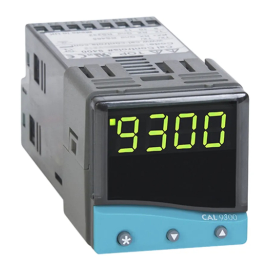
CAL Controls 3300 Application Manual
Installation and cabling of the communications option for controllers
Hide thumbs
Also See for 3300:
- Operating manual (39 pages) ,
- Manual (36 pages) ,
- Communications manual (25 pages)
Summary of Contents for CAL Controls 3300
- Page 1 Application Guide for Installation and Cabling of the Communications Option for CAL 3300 / 9300 / 9400 / 9500 Controllers 8th November 1999 Ver 1.10 Doc: 33010 Iss: 005...
- Page 2 Introduction The 3300 / 9300 / 9400 / 9500 series controllers can all be FITTING A COMMUNICATIONS INTERFACE BOARD ordered or retrofitted with either an RS232 or RS485 serial The RS232 and RS485 interface boards are interchangeable communications interface board. If the controller has the...
- Page 3 Insert the Nylon Screw into the 3mm diameter hole at the bottom left hand corner of the 3300 / 9300 / 9400 / 9500 board. Place spacer over Nylon screw thread. Screw the Nylon Full Nut onto the screw. Do not overtighten as this will damage the screw thread.
-
Page 4: Installation / Cabling
RS 485 interface units 10 11 12 13 14 15 10 11 12 13 14 15 10 11 12 13 14 15 PC Com Port 3300/9300 3300/9300 3300/9300 DB-9 Pin rear terminal unit 2 unit 1 Diagram 2 Diagram 3... - Page 5 Each RS485 interface has specific connection and Instrument 1 Instrument 2 Instrument ‘N’ termination biasing requirements which will be – – – detailed in their installation instructions. The general – – – principals are as follows. Terminations Because each wire is a transmission line, –...
-
Page 6: External Power Supply
If you have purchased the KK Systems RS232/485 converter drive all the connected controllers. The power you can from CAL Controls then the specific requirements for this derive from PC serial ports varies greatly from PC to PC, and converter are detailed here. Please note that the KK Systems... -
Page 7: Instrument Comms Settings
Instrument Comms Settings Immediately after power-up, both instrument, and PC comms (Debug) Commissioning and DBUG settings need to be made compatible before communication troubleshooting aid. Display shows when the between them is possible. Instrument defaults are shown instrument is transmitting or receiving data by below together with available options. -
Page 8: Configuring Instrument Comms Settings
Configuring Instrument Comms Settings This should also be done immediately after power-up, and To read or adjust comms settings is only possible from the instrument front panel. Baud rate and 9600 Press once display alternates BAUD On power-up the controller will display the self test (Default setting) and nonE sequence followed by Alternating... -
Page 9: Application Software
Cal 3300/9300/9400/9500 Modbus RTU return to ‘Auto Plot’ mode when finished. If possible you communications guide, and is available from CAL Controls Ltd. should also increase the ‘Refresh Frequency’ option in the CALCOMMS™ APPLICATION SOFTWARE ‘Select Units To Chart’... - Page 10 CAL Controls Ltd Bury Mead Road, Hitchin, Herts, SG5 1RT. UK Tel: + 44 (0)1462-436161 Fax: + 44 (0)1462-451801 email: support@cal-controls.co.uk http://www.cal-controls.com CAL Controls Inc 1580 S.Milwaukee Avenue, Libertyville, IL 60048. USA Tel: (847) 680-7080 Fax: (847) 816-6852 33010/5/1199...


Need help?
Do you have a question about the 3300 and is the answer not in the manual?
Questions and answers