Table of Contents
Advertisement
Quick Links
Data
Projector
Operating Instructions
Before operating the unit, please read this manual and supplied Quick Reference Manual
thoroughly and retain it for future reference.
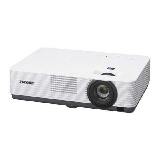
VPL-DX271/DX241/DX221
VPL-DW241
Not all models are available in all countries and area. Please check
with your local Sony Authorized Dealer.
© 2017 Sony Corporation
4-698-369-11 (1)
Advertisement
Table of Contents

Related Manuals for Sony VPL-DX271


Summary of Contents for Sony VPL-DX271
- Page 1 Before operating the unit, please read this manual and supplied Quick Reference Manual thoroughly and retain it for future reference. VPL-DX271/DX241/DX221 VPL-DW241 Not all models are available in all countries and area. Please check with your local Sony Authorized Dealer. © 2017 Sony Corporation...
-
Page 2: Table Of Contents
Table of Contents Overview Others Location and Function of Controls ..3 Indicators ..........29 Main Unit ........3 Messages List ........31 Terminal Panel ......4 Troubleshooting ........32 Remote Commander and Control Replacing the Lamp ......34 Panel Keys ......... 5 Cleaning the Air Filter ......36 When Using the Projector by Mounting It to a Ceiling ........37 Preparation... -
Page 3: Location And Function Of Controls
B Overview Location and Function of Controls Main Unit j Ventilation holes (exhaust) Caution Do not place anything near the ventilation holes as this may cause internal heat buildup. Do not place your hand near the ventilation holes and the circumference as this may cause injury. -
Page 4: Terminal Panel
INPUT A e Power Supply* Video: RGB/YP input terminal USB terminal (Type A)(5V/2A) * VPL-DX271/DX241/DW241 only b INPUT B If you use the power supply terminal, set “Power Supply” to “On” in the Video: HDMI input terminal Connection/Power menu (page 25). -
Page 5: Remote Commander And Control Panel Keys
Remote Commander and Control Panel Keys Remote Commander d Adjusting the image (page 11) ASPECT key (page 19) KEYSTONE key (page 14) PATTERN key (page 12) INPUT ECO MODE APA (Auto Pixel Alignment) key (page 14) MENU RESET Note Use this key when inputting a computer ENTER signal via the RGB input terminal RETURN... - Page 6 For details on ECO Mode settings, see *2: Use this key when inputting a computer signal. “Lamp Mode”, “With No Input” and “With Static Signal” on the Connection/ f Setting the energy–saving mode Power menu (page 25). easily g Infrared transmitter ECO MODE key Energy-saving mode can be set easily.
-
Page 7: Connecting The Projector
• The resolutions of the projected image may vary depending on the input terminals. • It is recommended that you set the resolution of your computer to 1024 × 768 pixels (VPL-DX271/ DX241/DX221) or 1280 × 800 pixels (VPL-DW241) for the external monitor. -
Page 8: Connecting A Video Equipment
• The HDMI terminal of this projector is not compatible with DSD (Direct Stream Digital) Signal or CEC (Consumer Electronics Control) Signal. • Use a high speed HDMI cable(s) on which the cable type logo is specified. (Sony products are recommended.) •... -
Page 9: Connecting To An External Device
• The HDMI terminal of this projector is not compatible with DSD (Direct Stream Digital) Signal or CEC (Consumer Electronics Control) Signal. • Use a high speed HDMI cable(s) on which the cable type logo is specified. (Sony products are recommended.) •... -
Page 10: Projecting An Image
B Projecting an Image Projecting an Image The size of a projected image depends on the distance between the projector and screen. Install the projector so that the projected image fits the screen size. For details on projection distances “Projection Distance” (page 44) and projected image sizes, see Input Video... -
Page 11: Adjusting The Projected Image
Adjusting the Projected image Focus Size (Zoom) Position Foot adjust Zoom ring button Front foot (adjustable) Rear feet Focus ring Projecting an Image... - Page 12 Display the patterns for adjusting an image Press the PATTERN key of the remote control to display the patterns for adjusting an image on the projected image. Press the PATTERN button again to return to the previous image. Pattern for adjusting an image Projecting an Image...
- Page 13 Adjusting with the foot adjust button You can adjust the position of the projected image by tilting the projector with the foot adjust button. 1 Press and hold the foot adjust button, then lift up the front of the projector to adjust the angle.
- Page 14 2 Use the V/v/B/b the keys to set the value. The higher the value, the narrower the top of the projected image. The lower the value, the narrower the bottom. Notes *1: Since the Keystone adjustment is an electronic correction, the image may be deteriorated. *2: VPL-DX271/DX241/DW241 only. Increase the number towards plus Increase the number...
-
Page 15: Turning Off The Power
• Do not turn off the projector soon after the lamp lights. It may cause a malfunction of the lamp (does not light ,etc.). • “Power Supply” is VPL-DX271/DX241/DW241 only. Unplug the AC power cord from the wall outlet. Turning off without displaying the confirmation message Press and hold the key on the unit for a few seconds (page 31). - Page 16 ECO gauge This gauge indicates the current effectiveness of the projector’s ECO function. (For details on the ECO function, see “ECO MODE key” (page 6) and “ECO” (page 25).) The leaf icons are displayed when the projector is shut down. The number of displayed icons varies according to how much energy is saved as a result of using the ECO function.
-
Page 17: Adjustments And Settings
B Adjustments and Settings Using a Menu If the next menu window is displayed, Using a MENU select the item according to the operations in step 3 and then press the ENTER key to register the setting. To return to the selection screen of the Note setting items, press the B or RETURN The menu displays used for the explanation... -
Page 18: The Picture Menu
The Picture Menu The Picture menu is used to adjust the picture for each input signal. Items Item descriptions Picture Mode Vivid: Projects the image with a bright, explicit, and vivid picture. Dynamic: Emphasizes the contrast to produce a dynamic and vivid picture. Standard: Provides an image which is natural and well balanced. -
Page 19: The Screen Menu
Items Item descriptions Aspect Changes the aspect ratio of the projected image (page 21). VPL-DX271/DX241/ 4:3: Displays the image to fit the maximum projected image size DX221: When the with an aspect ratio fixed to 4:3. computer signal is... - Page 20 Items Item descriptions Adjust Signal Adjusts the image of a computer signal. Use this item if the edge of the image is cut, or is not displayed properly. *2 *3 Automatically adjusts the projected image to an optimum quality when you press the ENTER key (page 5). Phase Adjusts the dot phase of the display pixel and the input signal.
- Page 21 *1: If you select “Normal,” the image is Aspect projected in the same resolution as the input signal without changing the aspect VPL-DX271/DX241/DX221 ratio of the original image. Input signal Recommended setting value and projected image Full1 *2: If you select “4:3,” the image is projected to fit the projected image size, regardless of the aspect ratio of the image.
- Page 22 VPL-DW241 *1: If you select “Normal,” the image is projected in the same resolution as the input signal without changing the aspect Input signal Recommended setting value and ratio of the original image. projected image *1 *2 *3 Full1 *2: If you select “Full2,” the image is projected to fit the projected image size, regardless of the aspect ratio of the image.
-
Page 23: The Function Menu
The Function Menu The Function menu is used for setting various functions of the projector. Items Item descriptions Presentation Timer Timer Set/Start: Sets the projecting time with the timer. Press the ENTER key to start counting. Count UP/Down Up/Down: Selects counting up or counting down of the set time. Volume The higher the value, the louder an audio volume and the lower the value, the lower the audio volume. -
Page 24: The Operation Menu
3 Enter the password again to confirm. Notes *1: You will not be able to use the projector if you forget your password. If you call qualified Sony personnel because you have forgotten the password, you will be asked to verify the projector’s serial number and your identity. -
Page 25: The Connection/Power Menu
The Connection/Power Menu The Connection/Power menu is used for setting for the connections and power. Items Item descriptions Lamp Mode High/Standard/Low/Auto : When set to “High,” the image becomes brighter, and power consumption becomes higher. When set to “Low,” power consumption is minimized; however, the image will be darker. When set to “Auto,”... - Page 26 Notes *1: This mode does not work for about three minutes after the lamp lights. A change in signal may not be detected depending on the input image. The lamp may become brighter at intervals if you continue to use the projector during lamp dimming. However, this is not a malfunction. If With No Input is set, it takes priority.
-
Page 27: The Installation Menu
Notes *1: Since the Keystone adjustment is an electronic correction, the image may be deteriorated. *2: VPL-DX271/DX241/DW241 only. *3: When “High Altitude Mode” is set to “On,” the speed of the fan increases, and the fan noise becomes slightly louder. -
Page 28: The Information Menu
The Information Menu The Information menu is used to check projector status, such as total usage time of the lamp. Items Item descriptions Model Name Displays the model name. Serial No. Displays the serial number. fH/fV Displays the horizontal/vertical frequency of the current input signal. Signal Type Displays the type of the current input signal. -
Page 29: Indicators
B Others Indicators You can check the projector status or abnormality by checking the lighting/flashing status of the ON/STANDBY indicator and WARNING indicator. If the indicators flash in red, address the problem in accordance with “Warning indicators and remedies” (page 30). WARNING ON/STANDBY indicator... - Page 30 If the indicators flash in a manner other than described above, unplug the AC power cord and make sure the ON/STANDBY indicator turns off, then plug the AC power cord into the wall outlet and turn on the projector. If the problem still persists, consult with qualified Sony personnel. Indicators...
-
Page 31: Messages List
Messages List When any of the messages listed below appears on the projected image, address the problem in accordance with the table below. Messages Meaning/Remedy Page Please clean the filter. Clean the air filter. Please replace the Lamp Replace the lamp with a new one and clean the air filter. The 34, 36 and clean the Filter. -
Page 32: Troubleshooting
Troubleshooting Before asking to have the projector repaired, try to diagnose the problem, following the instructions below. Symptoms Remedy Page The power is not turned Check if the AC power cord is firmly connected. – When the “Control Key Lock” is set to “On,” you cannot turn on the projector using the ?/1 key on the projector. - Page 33 • Check if the air filter is clogged. If it is clogged, clean or replace the air filter. • Check if the ventilation holes (exhaust/intake) are not blocked by walls or objects. Keep enough space around the unit. Note *1: VPL-DX271/DX241/DW241 only. Troubleshooting...
-
Page 34: Replacing The Lamp
Time” to “Standard” before turning off the unit (page 25). • If the lamp breaks, contact qualified Sony personnel. Do not replace the lamp yourself. • When removing the lamp, be sure to pull it out straight, by holding the designated location. - Page 35 Dispose according to applicable local, state/ province and federal laws. For additional information, see www.sony.com/mercury Notes • Be careful not to touch the glass surface of the lamp and a inside conductor. • The power will not turn on if the lamp is not secured properly.
-
Page 36: Cleaning The Air Filter
For details on purchasing/ fitting a new air filter, consult with the store Air filter where you purchased the projector, or contact qualified Sony personnel. Reattach the air filter cover to the unit. Caution If you continue to use the projector even... -
Page 37: When Using The Projector By Mounting It To A Ceiling
Attaching the dust cover When Using the When mounting the projector to the ceiling, Projector by you can attach the dust cover to the unit to Mounting It to a avoid dust from piling in the air filter. Place the air filter cover so that the dust Ceiling cover covers the air filter cover then insert the four claws (inside of the dust cover) into... -
Page 38: Cleaning The Air Filter And Its Surroundings
Cleaning the air filter and its Carrying the unit surroundings Note Turn off the unit, then remove the AC When carrying the unit, firmly grab its power cord from the wall outlet. nonslip surfaces with both hands to avoid from dropping it. Wipe the dust cover to remove the dust with a clean cloth. -
Page 39: Specifications
Items Descriptions Projection system 3 LCD system Display device Effective display VPL-DX271/DX241/DX221: 0.63 inch (16.0 mm), size 3 plate panels, Aspect ratio 4:3 VPL-DW241: 0.59 inch (15.0 mm), 3 plate panels, Aspect ratio 16:10 Effective picture VPL-DX271/DX241/DX221: 2,359,296 pixels (1024 ×... - Page 40 Storage humidity Power VPL-DX221: requirements 100 V to 240 V AC, 2.9 A -1.1 A, 50/60 Hz VPL-DX271/DX241/DW241: 100 V to 240 V AC, 3.0 A - 1.2 A, 50/60 Hz Power VPL-DX271: consumption 100 V to 120 V AC: 304 W...
- Page 41 Notes *1: For details, refer to “Acceptable Input Signals*1” on page 43. *2: VPL-DX271/DX241/DW241 only. *3: Not all optional accessories are available in all countries and area. Please check with your local Sony Authorized Dealer. *4: Information on accessories in this manual is current as of April 2017.
- Page 42 RGB input terminal (Mini D-sub Pin assignment 15-pin, female) HDMI terminal (HDMI, female) T.M.D.S. T.M.D.S. Data2+ Clock Shield Video input Power supply (red) R input for DDC T.M.D.S. T.M.D.S. Data2 Shield Clock – Video input (green) G T.M.D.S. N.C. Data2 – Video input (blue) B T.M.D.S.
- Page 43 Input terminal Acceptable Input Signals fH[kHz]/ Resolution RGB/ fV[Hz] HDMI Computer signal Input terminal 1280 × 800 49.7/60 fH[kHz]/ Resolution RGB/ fV[Hz] HDMI Digital TV signal 640 × 350 31.5/70 Input terminal 37.9/85 Signal fV[Hz] RGB/ HDMI 640 × 400 31.5/70 37.9/85 480i...
-
Page 44: Projection Distance
Projection Distance The projection distance is the distance between the front of the lens and the surface of the projected image. The following describes the projection distance and height from the center of the lens to edge of screen by each projected screen size. Height H is the height from the bottom of the projected image (top for ceiling mount) to A (determined by drawing a perpendicular line from the center of the lens to projected image surface). - Page 45 Ceiling Installation Height H from center of Center of lens lens to edge of screen Top side Projected image Projection distance L L: Projection distance L H: Height H from center of lens to edge of screen Projection Distance...
- Page 46 Projection distance table (VPL-DX271/DX241) Unit: m (inches) Height H from center of lens to edge Projected image size of screen Projection Minimum Maximum Distance L Diagonal D Width × Height Projection Projection Distance L Distance L 80 inch (2.03 m) 1.63 ×...
- Page 47 Projection distance table (VPL-DX221) Unit: m (inches) Height H from center of lens to edge Projected image size of screen Projection Minimum Maximum Distance L Diagonal D Width × Height Projection Projection Distance L Distance L 80 inch (2.03 m) 1.63 ×...
- Page 48 Projection distance table (VPL-DW241) Unit: m (inches) Height H from center of lens to edge Projected image size of screen Projection Distance L Minimum Maximum Diagonal D Width × Height Projection Projection Distance L Distance L 80 inch (2.03 m) 1.72 ×...
-
Page 49: Dimensions
Dimensions VPL-DX271/DX241/DW241 Center of Lens 325.1 (12 79.2 (3 Unit: mm (inches) VPL-DX221 Center of Lens 325.1 (12 79.2 (3 Unit: mm (inches) Dimensions... - Page 50 Front Center of Lens 79.2 (3 Unit: mm (inches) Side Unit: mm (inches) Dimensions...
- Page 51 Bottom 83.3 15.4 ( 15.4 ( 69.0 (2 ) 4.6 ( Holes for ceiling mount (M4, Depth 10 ( 28.5 (1 83.8 (3 224.0 (8 56.20 222.80 (8 Unit: mm (inches) Screw holes for the ceiling mount Use the screws with a length of 6 mm ( inches, minimum) to 10 mm ( inches, maximum) for the ceiling mount.
-
Page 52: Index
Index Gamma Mode ..........18 H (Horizontal) .........20 AC IN ............4 High Altitude Mode .........27 Acceptable input signal ......43 Hue ............18 Adjust Signal ........... 20 Air filter cover/Ventilation holes (intake) ..........3 APA ............5 Image Flip ..........27 Aspect ........... 5, 19, 21 Information menu ........28 Audio muting .......... - Page 53 About Trademarks Rear feet ............3 • Adobe and Adobe Acrobat are trademarks Remote commander ........5 or registered trademarks of Adobe Remote control detector ......3 Systems Incorporated in the United States Replacing the lamp ........34 and/or other countries. Reset ............18 • Kensington is a registered trademark of Kensington Technology Group.
- Page 54 Sony Corporation...
Need help?
Do you have a question about the VPL-DX271 and is the answer not in the manual?
Questions and answers