Table of Contents
Advertisement
Quick Links
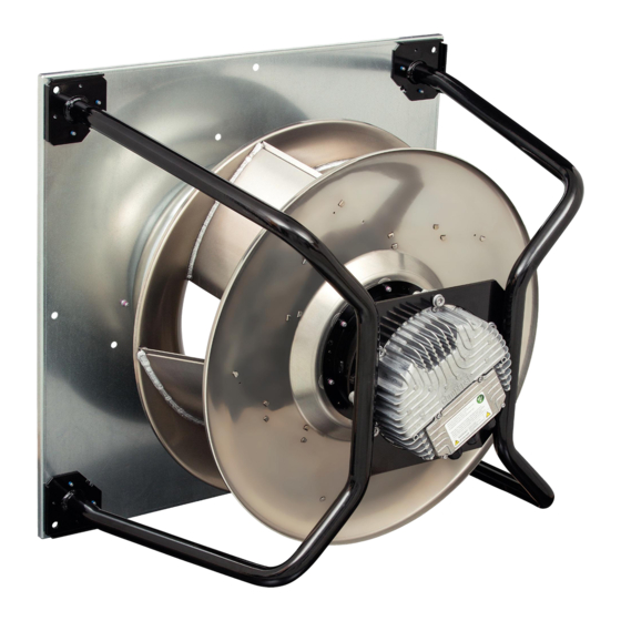
K3G560-PB31-61
ebm-papst Mulfingen GmbH & Co. KG
Bachmühle 2
D-74673 Mulfingen
Phone +49 (0) 7938 81-0
Fax +49 (0) 7938 81-110
info1@de.ebmpapst.com
www.ebmpapst.com
CONTENTS
Item no. 56891-5-9970 · ENU · Change 200264 · Approved 2019-02-08 · Page 1 / 16
ebm-papst Mulfingen GmbH & Co. KG · Bachmühle 2 · D-74673 Mulfingen · Phone +49 (0) 7938 81-0 · Fax +49 (0) 7938 81-110 · info1@de.ebmpapst.com · www.ebmpapst.com
Operating instructions
1. SAFETY REGULATIONS AND INFORMATION
Read these operating instructions carefully before starting work on the
device. Observe the following warnings to prevent malfunctions or
danger to persons.
These operating instructions are to be regarded as part of the device.
The device is only to be sold or passed on together with the operating
instructions.
These operating instructions may be duplicated and distributed to inform
about potential dangers and their prevention.
1
1.1 Hazard levels for warnings
1
1
These operating instructions use the following hazard levels to indicate
1
potentially hazardous situations and important safety regulations:
1
2
2
2
2
2
2
3
3
4
4
5
5
5
6
6
1.2 Staff qualifications
6
The device may only be transported, unpacked, installed, operated,
6
maintained and otherwise used by suitably qualified, trained and
6
authorized technical staff.
7
Only authorized specialists are permitted to install the device, to carry
8
out a test run and to perform work on the electrical installation.
9
10
1.3 Basic safety rules
11
12
The safety hazards associated with the device must be assessed again
13
following installation in the final product.
13
The locally applicable industrial safety regulations are always to be
13
observed when working on the device.
Keep the workplace clean and tidy. Untidiness in the work area
13
increases the risk of accidents.
Note the following when working on the device:
14
; Do not perform any modifications, additions or conversions on the
device without the approval of ebm-papst.
14
15
1.4 Voltage
15
; Check the device's electrical equipment at regular intervals; see
15
Chapter 6.4 Safety inspection.
16
; Replace loose connections and defective cables immediately.
DANGER
Indicates an imminently hazardous situation which will result in
death or serious injury if the specified actions are not taken.
Compliance with the instructions is imperative.
WARNING
Indicates a potentially hazardous situation which can result in
death or serious injury if the specified actions are not taken.
Exercise extreme caution while working.
CAUTION
Indicates a potentially hazardous situation which can result in
minor or moderate injury or damage to property if the specified
actions are not taken.
NOTE
A potentially harmful situation can occur and, if not avoided, can
lead to property damage.
DANGER
Electrically charged device
Risk of electric shock
→ When working on an electrically charged device, stand on a
rubber mat.
Advertisement
Table of Contents

Related Manuals for ebm-paps K3G560-PB31-61


Summary of Contents for ebm-paps K3G560-PB31-61
-
Page 1: Table Of Contents
Operating instructions K3G560-PB31-61 ebm-papst Mulfingen GmbH & Co. KG 1. SAFETY REGULATIONS AND INFORMATION Bachmühle 2 Read these operating instructions carefully before starting work on the D-74673 Mulfingen device. Observe the following warnings to prevent malfunctions or Phone +49 (0) 7938 81-0 danger to persons. -
Page 2: Safety And Protective Features
Operating instructions K3G560-PB31-61 WARNING 1.7 Mechanical movement Live terminals and connections even with device DANGER switched off Rotating device Electric shock Risk of injury to body parts coming into contact with the rotor or → Wait five minutes after disconnecting the voltage at all poles the impeller. -
Page 3: Storage
Operating instructions K3G560-PB31-61 1.11 Storage Conveying highly corrosive air, e.g. salt spray. Exception: devices ● designed for salt spray and correspondingly protected. ; Store the device, partially or fully assembled, in a dry place, Conveying air with high dust content, e.g. suctioning off sawdust. -
Page 4: Technical Data
Operating instructions K3G560-PB31-61 3. TECHNICAL DATA 3.1 Product drawing All dimensions in mm. Installed position: shaft horizontal (install support struts only vertically as illustrated) or rotor on bottom; rotor on top on request Cable diameter min. 4 mm, max. 10 mm, tightening torque 2±0.3 Nm Tightening torque 1.5 ±... -
Page 5: Nominal Data
Operating instructions K3G560-PB31-61 3.2 Nominal data 3.4 Technical description Motor M3G150-IF Weight 51.8 kg Size 560 mm Phase Motor size Nominal voltage / VAC Rotor surface Painted black Nominal voltage 380 .. 480 Electronics housing Die-cast aluminum range / VAC... -
Page 6: Mounting Data
Operating instructions K3G560-PB31-61 Approval EAC; CSA C22.2 No. 77 + CAN/CSA- 4. CONNECTION AND STARTUP E60730-1; UL 1004-7 + 60730-1 4.1 Mechanical connection With regard to cyclic speed loads, note that the rotating parts of the device are designed for a maximum of one million load CAUTION cycles. -
Page 7: Electrical Connection
Operating instructions K3G560-PB31-61 NOTE Device malfunctions possible Route the device's control lines separately from the supply line. → Maintain the greatest possible clearance. Recommendation: clearance > 10 cm (separate cable routing) NOTE Water ingress into wires or cables Water ingress at the customer end of the cable can damage the device. -
Page 8: Connection In Terminal Box
Operating instructions K3G560-PB31-61 4.2.3 Reactive currents 4.3.2 Connect cables to terminals WARNING Because of the EMC filter integrated for compliance with EMC limits (interference emission and immunity to interference), Live terminals and connections even with device reactive currents can be measured in the supply line even... -
Page 9: Factory Settings
Operating instructions K3G560-PB31-61 4.3.3 Cable routing Water must be prevented from reaching the cable gland along the cable. NOTE Damage caused by moisture penetration. Moisture can penetrate into the terminal box if water is constantly present at the cable glands. -
Page 10: Connection Diagram
Operating instructions K3G560-PB31-61 4.5 Connection diagram Conn. Designation Function/assignment CON1 L1, L2, L3 Power supply, phase, see nameplate for voltage range Protective earth CON2 RS485 interface for MODBUS, RSA; SELV CON2 RS485 interface for MODBUS, RSB; SELV CON2 Reference ground for control interface, SELV CON2 Function parameterizable (see “Optional interface functions”... -
Page 11: Configuration Options
Operating instructions K3G560-PB31-61 4.6 Configuration options Item no. 56891-5-9970 · ENU · Change 200264 · Approved 2019-02-08 · Page 11 / 16 ebm-papst Mulfingen GmbH & Co. KG · Bachmühle 2 · D-74673 Mulfingen · Phone +49 (0) 7938 81-0 · Fax +49 (0) 7938 81-110 · info1@de.ebmpapst.com · www.ebmpapst.com... -
Page 12: Equivalent Circuit Diagrams
Operating instructions K3G560-PB31-61 4.7 Equivalent circuit diagrams Item no. 56891-5-9970 · ENU · Change 200264 · Approved 2019-02-08 · Page 12 / 16 ebm-papst Mulfingen GmbH & Co. KG · Bachmühle 2 · D-74673 Mulfingen · Phone +49 (0) 7938 81-0 · Fax +49 (0) 7938 81-110 · info1@de.ebmpapst.com · www.ebmpapst.com... -
Page 13: Checking Connections
Operating instructions K3G560-PB31-61 4.8 Checking connections 4.10 Switching off the device ; Ensure isolation from supply (all phases). Switching off the device during operation: ; Make sure a restart is impossible ; Switch off the device via the control input. -
Page 14: Maintenance, Malfunctions, Possible Causes And Remedies
Operating instructions K3G560-PB31-61 6. MAINTENANCE, MALFUNCTIONS, POSSIBLE Ambient temperature Reduce the ambient too high temperature. Allow CAUSES AND REMEDIES the device to cool down. Do not perform any repairs on your device. Send the device to ebm- Impermissible Correct the operating papst for repair or replacement. -
Page 15: Vibration Testing
Operating instructions K3G560-PB31-61 Rotor Follow the Rotor NOTE position replacement position Damage to the device during cleaning sensor instructions sensor Malfunction possible calibration needs → Do not clean the device using a high-pressure cleaner.# Do error calibration. not use acid, alkali or solvent-based cleaning agents. -
Page 16: Disposal
Operating instructions K3G560-PB31-61 Abnormal acoustic At least every Replace device Power cables ● bearing noise 6 months Cables for internal wiring ● Vibration test Vibration tester, Recommended Clean impeller Electrolytic capacitors ● start-up or every 6 months or replace device...
Need help?
Do you have a question about the K3G560-PB31-61 and is the answer not in the manual?
Questions and answers