Sign In
Upload
Download
Table of Contents
Contents
Add to my manuals
Delete from my manuals
Share
URL of this page:
HTML Link:
Bookmark this page
Add
Manual will be automatically added to "My Manuals"
Print this page
×
Bookmark added
×
Added to my manuals
Manuals
Brands
Lorex Manuals
DVR
N882A38B
User manual
Lorex N882A38B User Manual
Hide thumbs
1
2
3
4
Table Of Contents
5
6
7
8
9
10
11
12
13
14
15
16
17
18
19
20
21
22
23
24
25
26
27
28
29
30
31
32
33
34
35
36
37
38
39
40
41
42
43
44
45
46
47
48
49
50
51
52
53
54
55
56
57
58
59
60
61
62
63
64
65
66
67
68
69
70
71
72
73
74
75
76
77
78
79
80
81
82
83
84
85
86
87
88
89
90
91
92
93
94
95
96
97
98
99
100
101
102
103
104
105
106
107
108
109
110
111
112
113
114
115
116
117
118
119
120
121
122
page
of
122
Go
/
122
Contents
Table of Contents
Troubleshooting
Bookmarks
Table of Contents
Table of Contents
Important Safeguards
General Precautions
Installation
Service
Use
Package Contents
Recorder Overview
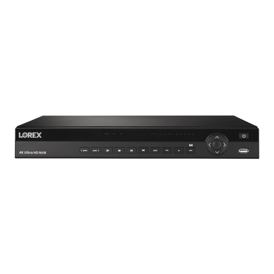
Front Panel
Back Panel
Basic System Setup
STEP 1: Connect Cameras
STEP 2: Connect Router
STEP 3: Connect Mouse
STEP 4: Connect Monitor
STEP 5: Connect Power
STEP 6: Upgrade Firmware to Latest Version (if Available)
Quick Access to System Information
Connecting Cameras to the Local Area Network (LAN)
Camera Installation
Installation Tips
Installing Cameras
Connecting Camera Extension Cables
Using the Mouse
Setting the Date & Time
Using the On-Screen Display
Navigation Bar
Quick Menu
Camera Toolbar
On-Screen Keyboards
Camera Image Settings
Recording
Video Recording Types
Configuring Recording Quality
Setting the Recording Schedule
Setting up Scheduled or Manual Recording
Configuring Hard Drive Overwrite
Playback
Playing Back Video from the Hard Drive
Playback Controls
Area Search
Video Clip Backup
Playing Back Video from a USB Drive
Backup
Formatting the USB Flash Drive
Backing up Video
Using Video Clip Backup
Viewing Backed up Files
Viewing Backed up Files on PC
Viewing Backed up Files on Mac
Lorex Player Controls
Motion Detection
Status Icons
Configuring Motion Detection
Active Deterrence
Automatic Deterrence Settings
Manually Activate Deterrence Features
Smart Motion Detection
Ensuring Accurate Person & Vehicle Detection
Configuring Person & Vehicle Detection
Searching for Person & Vehicle Detection Events (Smart Search)
Managing Passwords and User Accounts
User Accounts
Changing Passwords
Adding Users
Modifying Users
Deleting Users
Account Groups
Adding Groups
Modifying Groups
Deleting Groups
Using the Main Menu
Main Menu Overview
Camera Menu
Viewing Camera Status
Camera Firmware Versions
Upgrading Camera Firmware
Poe Manager
Configuring Snapshot Recording Settings
Configuring Video Overlay Settings
Creating Custom Channel Names
Information Menu
Hard Drive Information
Recording Information
Fan and CPU Status
Version Information
Event Information
Online Users
Network Load
Network Test
Bps
System Log
Settings Menu
Selecting DHCP or Static IP Address (TCP/IP)
Configuring System Ports (Connection)
Configuring IP Filter
Configuring Email Alerts
FTP (Advanced)
Configuring Switch Settings (Advanced)
P2P Setting
Configuring Video Loss Settings
Configuring Hard Drive Warnings
Configuring Network Warnings
Configuring Pre-Recording
Formatting the Hard Drive
Configuring Hard Drive Type
Configuring Hard Drive Groups (Advanced)
Configuring Holidays
Configuring General System Settings
Setting the Monitor Resolution (Display)
Configuring Sequence Mode
Saving Your System Configuration to a USB Thumb Drive
Restore Default Settings
Upgrading Firmware Manually
Automatic Firmware Upgrades
Shutdown
Connecting to Your System Using Smartphone or Tablet Apps
Connecting Remotely Using the Mobile App
Pan/Tilt/Zoom (PTZ) Cameras
Connecting PTZ Cameras to the Recorder
Basic PTZ Controls
Advanced PTZ Controls
Presets
Tours
Patterns
Autoscan
Connecting Audio Devices
Replacing the Hard Drive
Removing the Hard Drive
Installing a New Hard Drive
DDNS Setup (Advanced)
STEP 1: Port Forwarding
STEP 2: Create a Lorex Account
STEP 3: Activate Your Warranty
STEP 4: Sign up for a DDNS Account
STEP 5: Enable DDNS on the Recorder
Troubleshooting
Top Reasons Your Lorex Camera May Lose Video or Go Black
Going over Poe Budget will Result in Video Loss
When to Use a Poe Switch
Not Enough Power or Total Loss of It
Power Surge and Interference
Not Supported Display Output
Twisted, Bent or Damaged Cables
Outdated Firmware and Hardware
Issue with Compatibility
Low Internet Bandwidth
Technical Specifications
General
Inputs/Outputs
Display
Recording
Playback
Storage
Special Features
Smart Home
Connectivity
Additional Specifications
Notices
Fcc/IC
Modification
Advertisement
Quick Links
Download this manual
User Manual
N882 Series
Table of
Contents
Previous
Page
Next
Page
1
2
3
4
5
Advertisement
Table of Contents
Need help?
Do you have a question about the N882A38B and is the answer not in the manual?
Ask a question
Questions and answers
Related Manuals for Lorex N882A38B
DVR Lorex N882A63B User Manual
(122 pages)
Voice Recorder Lorex N882 Series Quick Setup Manual
(2 pages)
DVR Lorex N881 Series User Manual
(136 pages)
DVR Lorex N881A63B User Manual
(136 pages)
DVR Lorex N882A64B User Manual
(122 pages)
DVR Lorex N883 Series Quick Start Manual
4k wired nvr system (9 pages)
DVR Lorex N884 Series Quick Start Manual
(8 pages)
DVR Lorex N841 Series User Manual
(130 pages)
DVR Lorex N841A81 User Manual
(130 pages)
DVR Lorex N862A63B User Manual
(120 pages)
DVR Lorex N842A82 User Manual
(126 pages)
DVR Lorex N4K2-86BB User Manual
(126 pages)
DVR Lorex N846 Series Quick Start Manual
4k fusion wired nvr system (8 pages)
DVR Lorex Fusion N864 Series Quick Start Manual
4k 16ch wired nvr system (9 pages)
DVR Lorex Fusion N845 Series Quick Start Manual
(11 pages)
DVR Lorex Fusion N845A62 Quick Start Manual
(11 pages)
This manual is also suitable for:
N882 series
E861ab-e
N882a64b
Table of Contents
Print
Rename the bookmark
Delete bookmark?
Delete from my manuals?
Login
Sign In
OR
Sign in with Facebook
Sign in with Google
Upload manual
Upload from disk
Upload from URL


Need help?
Do you have a question about the N882A38B and is the answer not in the manual?
Questions and answers