Table of Contents
Advertisement
Quick Links
Advertisement
Table of Contents

Related Manuals for OWL OWLTrek WTO-S15


Summary of Contents for OWL OWLTrek WTO-S15
- Page 1 Optical Wavelength Laboratories OPERATIONS GUIDE OWLTrek Optical Time Domain Reflectometer (OTDR) Model Numbers: WTO-S15 / WTO-S13 / WTO-S35 Revision 1O Optical Wavelength Laboratories (OWL) N9623 West US Hwy 12 Whitewater, WI 53190 Phone: 262-473-0643 Internet: OWL-INC.COM OWL-INC.COM...
-
Page 2: Table Of Contents
SECTION 1: INTRODUCTION TABLE OF CONTENTS SECTION 1: INTRODUCTION Before You Begin ......1 About This Manual . - Page 3 SECTION 1: INTRODUCTION TABLE OF CONTENTS SECTION 4: TRACE STORAGE Stored Readings/Setup Menu ..... . . 13 Saving a Trace ......13 Loading a Previously Stored Trace .
-
Page 4: Before You Begin
SECTION 1: INTRODUCTION BEFORE YOU BEGIN All personnel testing optical fibers should be adequately trained in the field of fiber optics before using any fiber optic test equipment. If the user is not completely familiar with testing fiber optics, they should seek competent training. Such training can be acquired from a variety of sources, such as local hands-on training classes or online courses. -
Page 5: Description
SECTION 1: INTRODUCTION DESCRIPTION Upholding OWL’s commitment to high-quality, yet affordable, fiber optic test equipment, the OWLTrek OTDR from OWL enables fiber optic professionals to quickly and easily troubleshoot and locate optical faults in singlemode fibers. The OWLTrek is truly a hand-held unit, being one of the smallest OTDRs on the market today – easily able to fit into a shirt pocket – yet having capabilities of other OTDRs costing thousands of dollars more. -
Page 6: Precautions
SECTION 1: INTRODUCTION PRECAUTIONS Eye Safety NEVER look into the connector port of any fiber optic test or transmission equipment, patch cable, fiber link, or other installed fiber. Always assume that active laser equipment is attached to optical fibers, and is powered on. Do not run a test on the OTDR unless it is connected to the fiber under test, or the dustcap is firmly in place. -
Page 7: Ports
SECTION 1: INTRODUCTION PORTS Reset Button – resets the OTDR in case of malfunction Battery Charger Port or Visual Fault Locator Port – certain models include a charger port for recharging the Lithium Polymer battery when used with approved wall charger, and some models include a Visual Fault Locator port for troubleshooting USB Download Port –... -
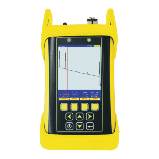
Page 8: Display
SECTION 1: INTRODUCTION DISPLAY Fiber # AUTO Fiber ID – name of the currently loaded fiber trace OTDR Test Mode – shows which test mode the OTDR is in – AUTO, USER, SEMI, or FILT VFL Indicator – shows the current VFL mode: blank = OFF;... -
Page 9: Indicator Leds
CHARGING STATUS – will be lit when charging through a transformer or USB port GREEN battery fully charged AUTO Fiber # ORANGE battery charging problem with battery and/or charger; contact OWL for service STANDBY STATUS Normal operation GREEN blinking STANDBY solid; press any key to “wake up” the device... -
Page 10: Section 2: Otdr Testing
SECTION 2: OTDR TESTING POWER ON/OFF POWER ON AUTO Fiber # Press to power on the OTDR. When the OTDR has completed startup, the trace area will either be blank, as shown at right, or will show the previously viewed trace. Continue below for more information about running a new OTDR trace. - Page 11 SECTION 2: OTDR TESTING SETTING TEST PARAMETERS SET WAVELENGTH Wave: 1550nm AUTO When using a dual-wavelength OTDR, traces can be run at either one or two wavelengths. To set the trace wavelength(s), press from the trace screen until the following menu options appear: EVENTS MENU...
-
Page 12: Range
SECTION 2: OTDR TESTING SETTING TEST PARAMETERS, cont. SETTING TRACE OPTIONS TRACE OPTIONS AUTO To see an additional menu of trace options, press from the trace CAPTURE MODE screen until the following menu options appear: PULSE WIDTH SAVE LOAD INDEX SETUP NUMBER OF 4096... -
Page 13: Range
SECTION 2: OTDR TESTING STARTING AN OTDR TRACE TESTING Once the OTDR parameters have been set, an OTDR trace can be run. Press from the trace screen until the following menu options appear: CURSOR LOCK TEST ZOOM starts an OTDR trace based upon the current OTDR parameters TEST During the OTDR test (as shown at right): 1550nm... -
Page 14: Section 3: Trace Analysis
SECTION 3: TRACE ANALYSIS OVERVIEW This section will provide a basic overview about how to analyze an OTDR trace, and will cover the different types of information that can be gathered from an OTDR trace, including: – event location; – fiber length measurement; –... -
Page 15: Fiber Length Measurement/Link Loss
SECTION 3: TRACE ANALYSIS FIBER LENGTH MEASUREMENT/LINK LOSS By placing the cursors at the beginning and ending points of the fiber trace, the Fiber # AUTO distance between the cursors will show a close approximation of the total length of the optical fiber link, as well as a close approximation of the total fiber link loss. -
Page 16: Reflectance Measurement
SECTION 3: TRACE ANALYSIS REFLECTANCE MEASUREMENT The reflectance of a specific event can be determined by placing the cursors on Fiber # AUTO either side of an event. The OTDR will show the reflectance in dB of the highest reflective event between the cursors. CURSOR PLACEMENT Proper cursor placement is important when determining the reflectance of a reflective event. -
Page 17: Section 4: Trace Storage
SECTION 4: TRACE STORAGE STORED READINGS AUTO Fiber # sets the Function Options Menu to allow access to Data Storage and Setup Menu options. The following soft-keys apply to data storage functions. SAVE SAVING A TRACE LOAD LOADING A PREVIOUSLY STORED TRACE 1550nm 6086m RFL dB... -
Page 18: Loading A Previously Stored Trace
SECTION 4: TRACE STORAGE LOADING A PREVIOUSLY STORED TRACE Previously stored traces can be loaded from memory for later on-screen analysis. STORED TRACES Trace Name Date Time The STORED TRACE menu may be accessed two ways: SM-BB-F1-F2:1 10/05/09 04:16PM SM-BB-F1-F2:2 10/05/09 04:17PM SM-BB-F1-F2:3... -
Page 19: Section 5: Otdr Setup
SECTION 5: OTDR SETUP MENUS AUTO Fiber # To access the SETUP MENU, either press MENU NAVIGATING THE MENU SYSTEM The arrow keys are used to navigate throughout the various menus and help screens in the OTDR. Green selection arrows highlight different menu options. moves the selection arrows to the next or previous menu option 1550nm jumps to the highlighted menu option... -
Page 20: Trace Setup Menu
SECTION 5: OTDR SETUP TRACE SETUP MENU CONFIGURE OPTIONS Enables TRACE SETUP MENU CONFIGURE OPTIONS the 2kHz tone and TRACE PARAMETERS visual fault FIBER ID TONE: locator CONFIGURE OPTIONS functions, available. SET BACKSCATTER COEFF. VISUAL FAULT LOCATOR: Press ENTER when done Press for help BACK... -
Page 21: User Information Menu
SECTION 5: OTDR SETUP USER INFORMATION MENU USER MENU Enter user name: USER NAME USER NAME USER PHONE ABCDEFGHIJKLM NOPQRSTUVWXYZ 0123456789:;< Use arrows to highlight letter then press the enter key. Tap the power button to abort. BACK SELECT EXIT USER NAME <-- SHIFT... -
Page 22: Display Preferences
SECTION 5: OTDR SETUP DISPLAY PREFERENCES DISPLAY OPTIONS FLIP MODE: MODE Sets the orientation of the LCD display. Three modes are available: FLIP LCD automatically alternates between portrait and DIMNESS landscape modes based upon the physical orientation of the OTDR BRIGHTNESS PORTRAIT display is always in portrait mode... -
Page 23: Power Options
SECTION 5: OTDR SETUP POWER OPTIONS POWER OPTIONS DIM TIME: DIM TIME Sets the time (in minutes) before the display will enter DIM mode. Range of values is 1 to 250. STANDBY TIME STANDBY TIME: OFF TIME Sets the time (in minutes) before the OTDR will enter STANDBY mode. Range of values is 2 to 250. -
Page 24: Utilities Menu
SECTION 5: OTDR SETUP UTILITIES MENU UTILITIES MENU HELP SET SYSTEM CLOCK Enter Date (MM/DD/YY) 06-25-10 Set System SET APD BIAS Clock FORMAT DATA FLASH Enter Time (HH:MM:SS) S e t s t h e 02:52:21:PM current time FACTORY RESET and date in the OTDR. -
Page 25: Manufacturer Setup
SECTION 5: OTDR SETUP UTILITIES MENU, CONT. UTILITIES MENU HELP * WARNING * SET SYSTEM CLOCK SET APD BIAS FORMAT DATA FLASH This will restore all user settings to factory FACTORY RESET defaults. Proceed? MANUFACTURER SETUP PROGRAM CPLD BACK SELECT EXIT Set real time clock Factory Reset... -
Page 26: Section 6: Operation/Maintenance
SECTION 6: OPERATION/MAINTENANCE CLEANING THE OTDR PORT This cleaning procedure applies to the OTDR port on the OWLTrek OTDR. Required Accessories: Isopropyl alcohol (91% or better) In-adapter fiber optic cleaning accessories, such as 2.5mm cleaning swabs or 2.5mm HUXCleaner™ In-adapter fiber optic inspection scope (LCD-based, 200x magnification or greater recommended) Compressed Air (optional) Below are procedures for “wet”... -
Page 27: Section 7: Appendices
Battery Replacement. The OWLTrek contains an internal Lithium Polymer battery. If the battery requires service, the device must be sent in to OWL. Unauthorized attempts to service the battery will void the product warranty. Cleaning. For accurate readings, the optical connector port on the OWLTrek and the connector on the patch cable should be cleaned prior to attaching them to each other.
Need help?
Do you have a question about the OWLTrek WTO-S15 and is the answer not in the manual?
Questions and answers