Table of Contents
Advertisement
Quick Links
Operator's
Manual
DANGER is used in this manual to warn of high
voltages capable of causing shock, burns, or death.
WARNING is used in this manual to warn
of possible personal injury.
CAUTION is used in this manual to warn
of possible equipment damage.
Florham Park, New Jersey 07932-1591 USA
Sales or service call 1 800 800-2726 (ASCO) www.ascopower.com
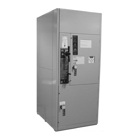
Bypass-Isolation Switches
H & P design 600 through 1200 A
600-1200 amp. sizes
7000 Series 7ATB
Automatic Transfer &
Refer to the outline and wiring drawings provided
with your 7000 Series ATB for all installation and
connection details and accessories.
Refer to Group 5 Controller User's Guide 381333-126
for ATS status display messages, time delays, pickup
& dropout settings, and adjustments.
An experienced licensed electrician must install the
7ATB.
Rating Label
Each 7000 Series 7ATB contains a rating label to
define the loads and fault circuit withstand/closing
ratings. Refer to the label on the Transfer Switch for
specific values.
Do not exceed the values on the rating label.
Exceeding the rating can cause personal injury
or serious equipment damage.
TABLE OF CONTENTS
. . . . . . . . . . . . . . . . . . . . . . . . . . . . .
Power Connections
Engine Starting & Auxiliary Circuits
. . . . . . . . . . . . . . . . .
. . . . . . . . . . . . . . . . . . . . . . . . . .
. . . . . . . . . . . . . . . . . . . . . .
. . . . . . . . . . . . . . . . . . .
. . . . . . . . . . . . . . .
. . . . . . . . . . . . . . . . . . . . . . . . .
section-page
1-1
. . . . . . . . . . . . . . . . . . . .
1-1
. . . . . .
1-2
1-2, 1-3, 1-4
2-1
. . . . . . . . . . . . . . . .
2-1
. . . . . . . . . . . .
2-1
. . . . . . . . . . . . . . . . . .
2-2
2-2
. . . . . . . . . . . . . . . . .
3-1, 3-2
3-3, 3-4
3-5, 3-6, 3-7
back cover
381333-193 D
Advertisement
Table of Contents

Subscribe to Our Youtube Channel
Related Manuals for ASCO POWER TECHNOLOGIES 7000 Series


Summary of Contents for ASCO POWER TECHNOLOGIES 7000 Series
-
Page 1: Table Of Contents
Bypass–Isolation Switches H & P design 600 through 1200 A Refer to the outline and wiring drawings provided with your 7000 Series ATB for all installation and DANGER is used in this manual to warn of high connection details and accessories. - Page 2 The Transfer Switch nameplate includes data for each Typical 7000 Series ATB catalog no. for overlapping specific 7000 Series ATB. Use the switch only within the neutral, 3 pole, 600 amp, 480 V, ATS in Type 1 enclosure: limits shown on this nameplate. A typical Catalog Number is shown below with its elements explained.
-
Page 3: Installation
SECTION 1 INSTALLATION Testing Power Conductors ASCO 7000 Series Automatic Transfer & Bypass– Isolation Switches (7ATBs) are factory wired and Do not connect the power conductors to the transfer tested. Field installation requires mounting and switch until they are tested. Installing power cables in... -
Page 4: Functional Test
INSTALLATION (continued) Engine Starting Contacts All customer connections, including the engine control contact connections, are located on terminal block TB which is mounted on the top right side of the enclosure. Refer to the wiring diagram provided with the automatic transfer switch and connect the engine start wires to the appropriate terminals. - Page 5 INSTALLATION (continued) Transfer Transfer Switch Transfer Switch Control Connected Connected Transfer Retransfer Test Delay HOLD FOR Normal Emergency Bypass 15 SECONDS GREEN observe Normal Emergency these lights Source Source Accepted Accepted GREEN Figure 1-2. Standard controls and indicators. Close the normal source circuit breaker.
- Page 6 INSTALLATION (continued) Transfer Transfer Switch Control Transfer Switch Connected Connected Transfer Retransfer Test Delay HOLD FOR Normal Emergency Bypass 15 SECONDS operate GREEN this switch observe Normal Emergency these lights Source Source Accepted Accepted GREEN Figure 1-3. Standard controls and indicators. 2 –...
-
Page 7: Testing & Service
1. Bypass and Isolate the Automatic Transfer Switch. Reasonable care in preventive maintenance will insure 2. Open the upper enclosure door. high reliability and long life for the 7000 Series 7ATB. 3. Separate the two quick disconnect plugs by squeez- An annual preventive maintenance program is recom- ing the latches. -
Page 8: Trouble-Shooting
* These are factory settings. Refer to Controller’s User’s Guide. If the problem is isolated to circuits on the controller or transfer switch, call your local ASCO Power Technologies sales office or ASI: in the United States, call 1–800–800–2726. Furnish the Serial No., Catalog No., and Bill of Material (BOM) No. -
Page 9: Bypassing & Isolating
SECTION 3 BYPASSING & ISOLATING BYPASSING THE ATS* This procedure explains how to Bypass the closed transfer switch contacts. Bypassing is required before the Transfer Switch can be tested or isolated. The Bypass Switch Handle must be in the OPEN position (green window indicator) and the Isolation Handle must be in the CONN [connected] position (window indicator). - Page 10 BYPASSING & ISOLATING (continued) To Bypass Normal Source* To Bypass Emergency Source* (Load connected to Normal Source) (Load connected to Emergency Source) The Transfer Switch Connected To Normal light is on The Transfer Switch Connected To Emergency light is on and Transfer Switch Connected To Emergency light is off.
-
Page 11: Isolating The Ats
BYPASSING & ISOLATING (continued) ISOLATING THE ATS NOTE: In the TEST position the transfer switch solenoid operator circuit is energized Isolating is required before any service work can be through secondary disconnects. performed on the automatic transfer switch (ATS). Refer to Figures 3–9, 3–10, 3–11, and 3–12. - Page 12 BYPASSING & ISOLATING (continued) 4. Open the lower enclosure door. Pull out both left and right side rails then use the two handles to roll out the To prevent the possibility of fatal electrical transfer switch. It can be safely inspected in this shocks and burns, bypass, isolate, and withdraw position.
-
Page 13: Return To Service
BYPASSING & ISOLATING (continued) 5. Remove the movable contact cover. RETURN TO SERVICE Use your thumb and fingers to squeeze the sides This procedure explains how to return the automatic inward until the contact cover is released from the transfer switch (ATS) to service after inspection and shaft clamp (both sides). - Page 14 BYPASSING & ISOLATING (continued) Do not close the isolation contacts unless TS CONNECTED Middle amber light the Transfer Switch (ATS) and Bypass should come on. TS TEST Switch are in the same position! TS ISOLATED 6. When the transfer switch is in the same position as the Bypass Switch handle, continue turning the Isolation Handle clockwise (about 8 turns) until the window shows CONN (connected).
- Page 15 BYPASSING & ISOLATING (continued) RETURN TO SERVICE continued* Indicator shows yellow when ATS This procedure explains how to return the Bypass Switch is bypassed to Handle to the OPEN position. The Bypass Handle must Emergency. be in the CLOSED position (yellow indicator on NOR- MAL or EMERGENCY) and the Isolation Handle must be in the CONN position (window).
-
Page 16: Index
2–1 disconnect plugs, 2–1 voltage checks, 1–3 phase rotation check, 1–3 HELP voltage, pickup and dropout settings preventive maintenance, 2–1 customercare@asco.com see Controller User’s Guide 800–800–ASCO problem, 2–2 381333–126 Printed in U.S.A. Copyright 2015 ASCO Power Technologies, L.P .
Need help?
Do you have a question about the 7000 Series and is the answer not in the manual?
Questions and answers