Advertisement
Table of Contents
DESCRIPTION
DC2769A-A-KIT is a kit of the DC2771A-A transmitter
board, featuring
LTC
6990, the DC2775A-A, featuring
®
LTC4124, and the DC2774A application-sized receiver
board featuring LTC4124. The DC2775A-A receiver can
KIT CONTENTS
1 × DC2771A-A (LTC6990) Transmitter Demo Board
1 × DC2775A-A (LTC4124) Receiver Demo Board
2 × DC2774A (LTC4124) Application-Sized Receiver Demo Board
PERFORMANCE SUMMARY
SYMBOL
PARAMETER
V
DC2771A-A Voltage Input
IN
I
DC2771A-A V
Current
IN
IN
V
DC2775A Battery Charge Voltage
BAT
V
DC2775A-A Battery Charge Voltage
BAT
I
DC2775A-A Charge Current
BAT
Air-Gap
Separation Between L
f
DC2771A-A Drive Frequency
DRIVE
f
DC2771A-A Resonant Tank Frequency
TX_TANK
f
DC2775A-A Resonant Tank Frequency
RX_TANK
BOARD PHOTO
Figure 1. DC2771A-A Picture
Specifications are at T
CONDITIONS
I
≤ 100mA
VIN
V
= 5V
IN
V
SEL1
V
SEL1
V
SEL1
V
SEL1
V
SEL1
V
BAT
and L
TX
RX
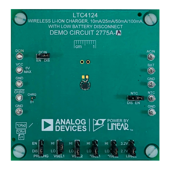
Figure 2. DC2775A-A Picture
10mA Wireless Li-Ion Charger
10mA Demonstration Kit
charge a single Li-Ion battery at up to 10mA with an air gap
of 0.5mm between the transmit and receive coils.
Design files for this circuit board kit are
All registered trademarks and trademarks are the property of their respective owners.
= 25°C
A
= V
, V
= GND
CC
SEL2
= HI, V
= HI
SEL2
= HI, V
= LO
SEL2
= LO, V
= HI
SEL2
= LO, V
= LO
SEL2
= 4.0V, I
= I
= GND
SEL1
SEL2
DEMO MANUAL
DC2769A-A-KIT
LTC6990/LTC4124
available.
MIN
TYP
MAX
4.5
5.5
100
4.2
4.35
4.2
4.1
4.0
10
0
0.5
0.75
1
1.4
1
Figure 3. DC2774A Picture
UNITS
V
mA
V
V
V
V
V
mA
mm
MHz
MHz
MHz
Rev. 0
1
Advertisement
Table of Contents

Related Manuals for Linear Analog Devices LTC6990


Summary of Contents for Linear Analog Devices LTC6990
- Page 1 DEMO MANUAL DC2769A-A-KIT LTC6990/LTC4124 10mA Wireless Li-Ion Charger 10mA Demonstration Kit DESCRIPTION DC2769A-A-KIT is a kit of the DC2771A-A transmitter charge a single Li-Ion battery at up to 10mA with an air gap board, featuring 6990, the DC2775A-A, featuring of 0.5mm between the transmit and receive coils. ®...
-
Page 2: Quick Start Procedure
DEMO MANUAL DC2769A-A-KIT QUICK START PROCEDURE Refer to Figure 5 to 8 for the proper measurement equip- 5. Set PS1 = 3.7V. If PS2 is used instead of Micro- ment setup, DC2775A-A mounting on DC2771A-A, and USB, set PS2 = 5V and turn on both power supplies follow the procedure below: simultaneously. - Page 3 DEMO MANUAL DC2769A-A-KIT QUICK START PROCEDURE BATTERY EMULATOR – RBAT1 3.7V DC 0.5A – Figure 5. DC2775A-A Top POWER DC2771A-A 5.0V DC USING MICRO-USB – 0.1A CABLE TO HOST OR A 5V ADAPTER. CONNECT TO A 5V POWER SUPPLY TO V AND GND TURRENTS Figure 6.
-
Page 4: Hardware Setup
DEMO MANUAL DC2769A-A-KIT HARDWARE SETUP Figure 8. DC 2774A on top of DC2771A-A in Operation Figure 9. Measuring Input or Output Ripple Note: All connections from equipment should be Kelvin connected directly to the board pins which they are connected on this diagram and any input or output leads should be twisted pair. -
Page 5: Operation
DC voltage on V pin. This DC source is then Featuring the LTC6990 fed into the internal linear battery charger to charge a The DC2771A-A is a wireless power transmitter board Li-Ion battery. using LTC6990 oscillator. The NMOS, M1(see DC2771A-A As shown in Figure 11, when the LTC4124 receives more... -
Page 6: Parts List
DEMO MANUAL DC2769A-A-KIT PARTS LIST ITEM REFERENCE PART DESCRIPTION MANUFACTURER/PART NUMBER DC2771A-A: Required Circuit Components CAP ., 4.7μF, X5R, 10V, 10%, 0402 TDK, C1005X5R1A475K050BC CAP ., 10μF, X5R, 6.3V, 20%, 0402 MURATA, GRJ155R60J106ME11D CTx2 CAP ., 1800pF, C0G, 50V, 5%, 0603 MURATA, GRM1885C1H182JA01D LTx1 IND., 7.5μH, WIRELESS CHRG. - Page 7 DEMO MANUAL DC2769A-A-KIT SCHEMATIC DIAGRAM Rev. 0 Information furnished by Analog Devices is believed to be accurate and reliable. However, no responsibility is assumed by Analog Devices for its use, nor for any infringements of patents or other rights of third parties that may result from its use. Specifications subject to change without notice.
- Page 8 DEMO MANUAL DC2769A-A-KIT SCHEMATIC DIAGRAM Rev. 0...
- Page 9 DEMO MANUAL DC2769A-A-KIT SCHEMATIC DIAGRAM Rev. 0...
- Page 10 DEMO MANUAL DC2769A-A-KIT ESD Caution ESD (electrostatic discharge) sensitive device. Charged devices and circuit boards can discharge without detection. Although this product features patented or proprietary protection circuitry, damage may occur on devices subjected to high energy ESD. Therefore, proper ESD precautions should be taken to avoid performance degradation or loss of functionality. Legal Terms and Conditions By using the evaluation board discussed herein (together with any tools, components documentation or support materials, the “Evaluation Board”), you are agreeing to be bound by the terms and conditions set forth below (“Agreement”) unless you have purchased the Evaluation Board, in which case the Analog Devices Standard Terms and Conditions of Sale shall govern.
Need help?
Do you have a question about the Analog Devices LTC6990 and is the answer not in the manual?
Questions and answers