Table of Contents
Advertisement
Quick Links
Advertisement
Table of Contents
Troubleshooting

Subscribe to Our Youtube Channel
Related Manuals for Teledyne SFG-20 Series


Summary of Contents for Teledyne SFG-20 Series
- Page 1 SFG-20X 5 &10 MHz Arbitrary/ Function User Waveform Generators Manual...
- Page 2 Safety Summary The following safety precautions apply to both operating and maintenance personnel and must be observed during all phases of operation, service, and repair of this instrument. Before applying power, follow the installation instructions and become familiar with the operating instructions for this instrument. If this device is damaged or something is missing, contact the place of purchase immediately.
- Page 3 hazard and appear throughout this manual. Follow all instructions contained in these statements. statement calls attention to an operating procedure, practice, or WARNING condition, which, if not followed correctly, could result in injury or death to personnel. statement calls attention to an operating procedure, practice, or condition, CAUTION which, if not followed correctly, could result in damage to or destruction of part or all of the product.
- Page 4 CE Declaration of Conformity The power supply meets the requirements of 2006/95/EC Low Voltage Directive and 2004/108/EC Electromagnetic Compatibility Directive with the following standards. Low Voltage Directive z EN61010-1: 2001 z EN61010-031: 2002+A1: 2008 EMC Directive z EN 61326-1:2006 z EN 61000-3-2: 2006+A2: 2009 z EN 61000-3-3: 2008 Safety Symbols Refer to the user manual for warning information to avoid hazard or...
-
Page 5: Introduction Of Sfg-20X Series
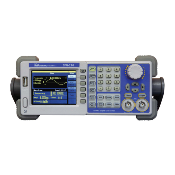
Introduction of SFG-20X Series The manual covers the following two types of SFG-20X Series Function/Arbitrary Waveform Generators: SFG-210 and SFG-205. SFG-20X Series Function/Arbitrary Waveform Generators adopt the direct digital synthesis (DDS) technology, which can provide stable, high-precision, pure and low distortion signals. Its combination of excellent system features, easiness in usage and versatile functions makes this generator a perfect solution for your job now and in the future. - Page 6 DDS technology provides precise, stable and low distortional output signal. 3.5’TFT color LCD display. 125MSa/s sampling rate, 14-bit resolution. Frequency characteristics: Sine: 1µHz to 30MHz Square: 1µHz to 10 MHz Ramp: 1µHz to 300kHz Pulse: 500µHz to 5MHz White Noise: 10MHz bandwidth (-3dB) Arbitrary: 1µHz to 5MHz 5 standard waveforms: Sine, Square, Ramp, Pulse, Noise Self-defined arbitrary waveform...
-
Page 7: Table Of Contents
Catalogue General Safety Summary ................. II Introduction of SFG-20X Series ..............VI 1. Getting Started ................... 1 1.1. General Inspection ................2 1.2. Handle Adjustment ................2 1.3. The Front/Rear Panel ............... 3 1.4. To Set a Waveform ................7 1.5. - Page 8 2.15. How to Use the Built-in Help System .......... 83 3. Application and Examples ................ 84 3.1. Example 1:Generate a Sine Wave ..........85 3.2. Example 2:Generate a Square Wave ..........87 3.3. Example 3:Generate a Ramp Wave ..........89 3.4.
-
Page 9: Getting Started
1. Getting Started This chapter covers the following topics: General Inspection Handle Adjustment The Front/Rear Panel To Set a Waveform To Set Modulate/Sweep/Burst To Set Output To Use Digital Input To Use Store/Utility/Help Function... -
Page 10: General Inspection
1.1. General Inspection When you get a new SFG-20X Series Function/Arbitrary Waveform Generator, you are suggested to take the following steps to inspect the instrument. 1. Inspect the shipping container for damage. If there are damages in the packing or foam, keep them until the whole machine and the accessories pass the electric and mechanical testing. -
Page 11: The Front/Rear Panel
To adjust the handle position of SFG-20X Function/Arbitrary Waveform Generator, please grip the handle by the sides and pull it outward. Then, make the handle rotate to the desired position. Figure 1- 1 Viewing Position and Carrying Position 1.3. The Front/Rear Panel... - Page 12 When you get a new SFG-20X Series Function/Arbitrary Waveform Generator, first you need to understand how to operate the front/rear panel correctly. This chapter will make a brief introduction and description for the operation and functions of the front/rear panel. The SFG-20X Series Function/Arbitrary Waveform Generator has a clear and simple front panel.
- Page 13 Figure 1- 3 Front Panel of SFG-20X Series 1. Display 2. Return Key 3. Waveform Selection Keys 4. Number Keypad 5. Knob 6. Cursor Keys 7. Manual Trigger Key (Sweep and Burst only) 8. Output Enable Key 9. Output BNC Connector Sync BNC Connector Help Menu Key Modulation/Sweep/Burst Keys...
- Page 14 17. USB Connector Figure 1- 4 Rear Panel of SFG-20X Series 1. USB Interface 2. AC Input Receptacle Waveform Menu Options Display area Parameter area Figure 1- 5 Display Interface (Sine Wave is the default display signal)
-
Page 15: To Set A Waveform
Character definitions in this User Manual: The signs for buttons in this manual are the same as the panel buttons. Please note that, the signs for the functional buttons on the operation panel are represented by squared words, such as Sine , which represents the transparent functional key with Sine on it on the front panel, while the menu buttons are represented by brighten words such as Freq, which means the... - Page 16 Figure 1- 7 Sine Signal Display Interface As is shown in Figure 1- 7, the default signal parameters are: 1 kHz frequency, 4.0 Vpp amplitude and 0 Vdc offset. 2. Press Square button, and the waveform window displays square waveform. SFG-20X Series Generator can generate square signal with a frequency from 1µHz to 10MHz and variable duty cycle.
- Page 17 4.0Vpp amplitude, 0Vdc offset and 50% duty cycle. 3. Press Ramp button, and the waveform window displays ramp waveform. SFG-20X Series Generator can generate ramp signal with a frequency of from 1µHz to 300kHz and variable symmetry. Figure 1- 9 Ramp Signal Display Interface As is shown in Figure 1- 9, the default signal parameters are: 1kHz frequency, 4.0Vpp amplitude, 0Vdc offset and 50% symmetry.
- Page 18 Figure 1- 10 Pulse Signal Display Interface As is shown in Figure 1- 10, the default signal parameters are: 1kHz frequency, 4.0Vpp amplitude, 0Vdc offset, 200µs pulse width. 5. Press Noise button, and the waveform window displays noise waveform. SFG-20X Series Generator can generate noise signal with a band width up to 10MHz.
- Page 19 6. Press Arb button, and the waveform window displays arbitrary waveform. SFG-20X Series Generator can generate repeatable arbitrary waveform signals with at most 16 kpts and 5 MHz frequency. Figure 1- 12 Arbitrary Waveform Signal Display Interface As is shown in Figure 1- 12, the default signal parameters are: 1 kHz frequency, 4.0 Vpp amplitude and 0 mVDC offset.
-
Page 20: To Set Modulate/Sweep/Burst
1.5. To Set Modulate/Sweep/Burst As shown in Figure 1- 13, there are three buttons on the front panel, which are used for modulation, sweep and burst settings. The instructions below will help you familiarize with the setting of these functions. Figure 1- 13 Modulate/Sweep/Burst Button Press Mod button, the modulated waveforms will be generated. - Page 21 2. Press Sweep button, sine, square, ramp or arbitrary waveform can be swept (pulse, noise and DC can not be swept). In the sweep mode, SFG-20X Series generate signal with variable frequencies. Figure 1- 15 Sweep Waveform Display Interface 3. Press Burst button, burst for sine, square, ramp, pulse or arbitrary waveform can be generated.
-
Page 22: To Set Output
Term Explanation Burst: Output waveforms with set cycle times. Burst can last for certain times of waveform cycle (N-Cycle Burst) or be controlled by external gated signals (Gated Burst). Burst applies to all kinds of waveforms, but noise can only be used in gated burst. Generally it is called burst function within every signal generator. -
Page 23: To Use Digital Input
1.7. To Use Digital Input As is shown in Figure 1- 18, there are three sets of buttons on the operation panel, which are direction button, the knob and the keypad. The instruction below will help you familiarize with the digital input function. Figure 1- 18 Front Panel Digital Input 1. -
Page 24: To Use Store/Utility/Help Function
1.8. To Use Store/Utility/Help Function As is shown in Figure 1- 19, there are three buttons on the operation panel, which are used to call the store/recall, utility and help function. The instruction below will help you familiarize with these functions. Figure 1- 19 Store/Recall Utility and Help Button 1. -
Page 25: Operating Your Generator
2. Operating Your Generator Up to now you have got a brief understanding about SFG-20X series with the front/rear panel, every function control area and keys. You should also know how to set your Function/Arbitrary Waveform Generator for your usage. If you are not familiar with these operations, you are suggested to read chapter one ‘Getting Started’... -
Page 26: To Set Sine Signals
2.1. To Set Sine Signals Press Sine button to call the sine operation. The sine waveform parameters are set by using the sine operation menu. The parameters of sine waveforms are: frequency/period, amplitude/high level, offset/low level and phase. Different sine signals are generated by setting these parameters. - Page 27 Figure 2- 2 Table2- 1 Menu Explanations of Sine Waveform Function Explanations menu Set the signal frequency or period; Freq/ The current parameter will be switched at a Period second press. Set the signal amplitude or high level; Ampl/ The current parameter will be switched at a HLevel second press.
- Page 28 to change its value. Figure 2- 3 Setting the Frequency Instruction: When using the keypad to enter the digit, you can use the left direction button to move the cursor backward and delete or change the value of the previous digit. To Set the Output Amplitude 1.
- Page 29 2. Input the desired Amplitude Use the keypad or the knob to input the desired value, choose the unit, and press the corresponding button. Figure 2- 4 Setting the Amplitude To Set the Output Offset Press Sine →Offset, to set the offset. The offset shown on the screen when the instrument is powered is the default value or the set value beforehand.
- Page 30 Figure 2- 5 Setting the Offset...
-
Page 31: To Set Square Signals
2.2. To Set Square Signals Press Square button to call the Square operation. The square waveform parameters are set by using the Square operation menu. The parameters of Square waveforms are: frequency/period, amplitude/high level, offset/low level, phase and duty. As is shown in Figure 2- 6, select Duty. Cursor is located in the duty parameter area in the parameter display window, and users can set the duty value here. - Page 32 Figure 2- 7 Table2- 2 Menu Explanations of Square Waveform Function Settings Explanation Menu Set the signal frequency or period; Freq/ The current parameter will be switched at a Period second press. Set the signal amplitude or high level; Ampl/ The current parameter will be switched at a HLevel second press.
- Page 33 Use the keypad or the knob to input the desired value, choose the unit, and press the corresponding button. The generator will change the waveform immediately. Figure 2- 8 Setting the Duty Cycle...
-
Page 34: To Set Ramp Signals
2.3. To Set Ramp Signals Press Ramp button to call the ramp operation. The ramp waveform parameters are set by using the ramp operation menu. The parameters for ramp waveforms are: frequency/ period, amplitude/ high level offset/ low level, phase and symmetry. As is shown in Figure 2- 9, in the soft key menu, select Symmetry. - Page 35 Figure 2- 10 Table2- 3 Menu Explanations of Ramp Waveform Function Settings Explanation Menu Set the signal frequency or period; Freq/ The current parameter will be switched at a Period second press. Set the signal amplitude or high level; Ampl/ The current parameter will be switched at a HLevel second press.
- Page 36 2. Input the desired Symmetry Use the keypad or the knob to input the desired value, choose the unit, and press the corresponding button. The generator will change the waveform immediately. Figure 2- 11 Setting the Symmetry...
-
Page 37: To Set Pulse Signals
2.4. To Set Pulse Signals Press Pulse button to call the pulse operation. The pulse waveform parameters are set by using the pulse operation menu. The parameters for pulse waveforms are: frequency/period, amplitude/high level, offset/low level, pulse width/Duty and Rise/Fall. As is shown in Figure 2- 12, in the soft key menu, select PulWidth. - Page 38 Figure 2- 13 Table 2- 4 Menu Explanations of Pulse Waveform Function Explanation Menu Set the signal frequency or period; Freq/ The current parameter will be switched at a Period second press. Set the signal amplitude or high level; Ampl/ The current parameter will be switched at a HLevel second press.
- Page 39 2. Input the desired Pulse Width Use the keypad or the knob to input the desired value, choose the unit, and press the corresponding button. The Generator will change the waveform immediately. Figure 2- 14 Setting the Pulse Width To Set the Rising Edge 1.
- Page 40 Figure 2- 15 Setting the Rise edge...
-
Page 41: To Set Noise Signals
2.5. To Set Noise Signals Press Noise button to call the Gaussian White noise operation. The noise waveform parameters are set by using the noise operation menu. The parameters for noise waveforms are: Stdev and mean. As is shown in Figure 2- 16, in the soft key menu, select Stdev, Cursor is located in the Stdev parameter area in the parameter display window, and users can set the Stdev value here. - Page 42 Figure 2- 17 Table 2- 5 Menu Explanations of Noise Waveform Function Settings Explanation Menu Stdev Set the signal standard deviation Mean Set the signal mean...
-
Page 43: To Set Arbitrary Signals
2.6. To Set Arbitrary Signals Press Arb button to call the Arb operation. The Arb waveform parameters are set by using the Arb operation menu. The Arb signal consists of two types: the system built-in waveform and the user-definable waveform. The parameters for Arb waveforms are: frequency/period, amplitude/high level, offset/ low level and phase. - Page 44 Figure 2- 19 Table 2- 6 Menu Explanations of Arb Waveform (Page 1/2) Function Settings Explanation Menu Set the signal frequency or period; Freq/ The current parameter will be switched at Period a second press. Set the signal amplitude or high level; Ampl/ The current parameter will be switched at HLevel...
- Page 45 To select the built-in Arbitrary Waveform There are forty-eight built-in Arbitrary Waveforms and user-definable Arbitrary Waveforms inside the Generator. To select one of them, follow the instructions below: Press Arb →Load Wform, to enter the interface below. Figure 2- 21 Table 2- 8 Menu Explanations of Built-in Arbitrary Waveform Function Settings...
- Page 46 Figure 2- 22 Table 2- 9 Menu Explanations of Built-In Arbitrary Waveform Function Settings Explanation Menu Common Select common waveform. Math Select math waveform. Project Select project waveform. Winfun/ Select windows function Triangle /triangle waveform. Select Validate the built-in waveform. Figure 2- 23 Common Built-In Arbitrary Waveform interface Table 2- 10 Menu Explanations of Common Built-In Arbitrary Waveform Function...
- Page 47 Figure 2- 24 Math Built-In Arbitrary Waveform Interface Table 2- 11 Menu Explanations of Math Built-in Arbitrary Waveform Function Settings Explanation Menu ExpFall Select the built-in exponential fall waveform. ExpRise Select he built-in exponential rise waveform. LogFall Select the built-in logarithmic fall waveform. LogRise Select the built-in logarithmic rise waveform.
- Page 48 Table 2- 12 Menu Explanations of Project Built-in Arbitrary Waveform Function Settings Explanation Menu Select the built-in electrocardiogram (ECG) signal Cardiac waveform. Quake Select the built-in loma prieta earthquake waveform. Select built-in swept-frequency cosine Chirp waveform. TwoTone Select the built-in two tone signal waveform. Select the built-in sin wave with white noise waveform.
- Page 49 Acot Select the built-in inverse cotangent waveform. 2. To Select the Stored Waveform Press Arb →Load Wform->Stored Wforms, and enter the following interface. As is shown in Figure 2- 27, use the direction keys or knob to choose the corresponding arbitrary waveform and press Select. Figure 2- 27 Stored Wform Display Interface...
-
Page 50: To Generate The Modulated Waveform
2.7. To Generate the Modulated Waveform Use the Mod button to generate modulated waveform.SFG-20X Series can generate AM, FM, ASK, FSK, PM, PWM and DSB-AM modulated waveforms. Modulating parameters vary with the types of the modulation. In AM, users can set the depth, modulating frequency, modulating waveform and carrier waveform;... - Page 51 The modulated waveform consists of two parts: the carrier waveform and the modulating waveform. In AM, the amplitude of the carrier waveform varies with the instantaneous voltage of the modulating waveform. The parameters for the AM are in Figure 2- 29 Press Mod →Type→...
- Page 52 The modulated waveform consists of two parts: the carrier waveform and the modulating waveform. In FM, the frequency of the carrier waveform varies with the instantaneous voltage of the modulating waveform. The parameters for the FM are as shown in Figure 2- 30. Figure 2- 30 Setting Interface of FM Waveform Parameter Press Mod →Type→...
- Page 53 Term Explanation Frequency Deviation The deviation should be equal to or less than the carrier waveform frequency. The sum of the deviation and the carrier frequency should be equal to or less than maximum frequency of the selected function. ASK is a form of modulation that represents digital data as variations in the amplitude of a carrier wave.
- Page 54 Press Mod →Type→ ASK, to enter the following menu. Figure 2- 33 Table 2- 16 Menu Explanations of the ASK Parameters Function Settings Explanation Menu Set the frequency at which the output amplitude shifts between carrier Key Freq amplitude and zero (internal modulation only): 2mHz~50kHz.
- Page 55 The FSK Modulation is a modulation method, the output frequency of which switches between two the pre-set frequencies (carrier waveform frequency and the hop frequency). The frequency at which the output frequency switches is called the key frequency. Figure 2- 34 Setting Interface of FSK Waveform Parameter Press Mod →Type→...
- Page 56 The modulated waveform consists of two parts: the carrier waveform and the modulating waveform. In PM, the phase of the carrier waveform varies with the instantaneous voltage level of the modulating waveform. The parameters for the PM are as shown in Figure 2- 36. Figure 2- 36 Setting Interface of PM Waveform Parameter Press Mod →Type →PM, enter the following interface.
- Page 57 Frequency range: 2mHz~20kHz Phase Range from 0° ~ 360°. Type Phase modulation Sine Square Triangle Choose the modulating waveform. Shape UpRamp To change the carrier waveform parameter, DnRamp press Sine, Square, Ramp, Arb Noise The modulated waveform consists of two parts: the carrier waveform and the modulating waveform, the carrier waveform is only pulse.
- Page 58 Figure 2- 39 Table 2- 19 Menu Explanations of the PWM Parameters Function Settings Explanation Menu modulating waveform PWM Freq frequency. 2mHz~20kHz Width Dev Set the width or Duty range. Duty Dev Type Amplitude modulation. Sine Square Triangle Choose the modulating waveform. Shape UpRamp The carrier waveform is pulse.
- Page 59 Set the modulating waveform frequency. DSB Freq Frequency range: 2mHz~20kHz Type DSB-AM Amplitude modulation. Sine Square Triangle Choose the modulating waveform. Shape UpRamp To change the carrier waveform parameter, DnRamp press Sine, Square, Ramp, Arb Noise...
-
Page 60: To Generate Sweep
2.8. To Generate Sweep In the frequency sweep mode, the function generator ‘steps’ from the start frequency to the stop frequency at the sweep time you specify. Sweep can be generated by sine, square, ramp or arbitrary waveforms (pulse, noise and DC are not allowed). - Page 61 Figure 2- 43 Table 2- 21 Menu Explanations of Waveform Sweep (Page 1/2) Function Settings Explanation Menu Set the time span of the sweep in which Swp Time the frequency changes from the start frequency to stop frequency. Stop Freq Set the stop frequency of the sweep;...
-
Page 62: To Generate Burst
2.9. To Generate Burst Burst function can generate versatile waveforms in burst, which can last specific times of waveform cycle (N-Cycle burst), or when external gated signals (gated burst) is applied, any waveform could be used, but noise can only be used in Gated Burst. - Page 63 Set the N-Cycle Burst Press Burst → N Cycle, to enter the following interface. Figure 2- 46 Table 2- 23 Menu Explanations of the N-Cycle Parameters(Page 1/2) Function Settings Explanation Menu Period Set the burst Period. Start Set the start phase of the burst. Phase NCycle Use the N-Cycle mode.
- Page 64 N-Cycle/Gated N-Cycle has specific number of waveform cycles, and every burst is activated by a trigger event. Gated burst use external source to control burst as when to be activated. Figure 2- 47 Table 2- 24 Menu Explanations of the N-Cycle Parameters (Page2/2) Function Settings Explanation...
- Page 65 Delay Set the time delay between the trigger input and the start of the N-Cycle burst. The max delay is 240ns. Set the Gated Burst Press Burst →Gated, to enter the following interface. Figure 2- 48 Table 2- 25 Menu Explanations of the Gated Burst Parameters Function Settings Explanation...
-
Page 66: To Store And Recall
2.10. To Store and Recall Press Store/Recall button to enter the following interface. You can save or recall the state documentation inside the generator. The state file on the U Disk is also allowed to recall or delete. File names can only be English. User can only recall or delete the data documentation you save via CSV of the Oscilloscopes. - Page 67 About the Browser The directory selection shift is done by the direction keys. In the directory mode, pressing the right key will open the lower directory while the left key will fold the directory. Up and down key are used to shift between the directories; To Save the Instrument State Users are allowed to store the instrument state in any of the 10 non-volatile memories.
- Page 68 To Use USB Storage As is shown in Figure 2- 51, the storage location is divided into: The internal storage Local(C :) and the U Disk storage USB Device (A :). At the left side of the front panel, there is a USB interface. When a USB storage is connected, the storage menu will show ‘USB Device (A:)’.
- Page 69 Remove the USB Device from the interface. The system will inform you ‘USB flash device plug out’, and the ‘USB Device (A :)’ in the storage menu will disappear. Note: USB Device can only be used by U Disk; portable hard disk is not supported.
- Page 70 Figure 2- 53 Table 2- 27 Menu Explanation of File Storage Function Settings Explanation Menu Input English input. Type Select Select the current character. Delete Delete the current character. Save Store the file with the current name 1. English Input The alphnumeric input interface is as shown in Figure 2- 54, to save a file named ‘NEWFILE’, follow the steps below: Figure 2- 54 Alphanumeric Input Interface...
- Page 71 Repeat this until you have inputted ‘NEWFILE’. (3) Edit the File Name When you have entered a wrong character, move the cursor to the wrong character to be deleted and press Delete to remove it. Reenter the file name. (4) Press Save, to finish and save the file.
-
Page 72: To Set The Utility Function
2.11. To Set the Utility Function With the Utility Function, you can set the parameters of the generator such as: DC On/Off, Sync On/Off, Output Parameter, Interface Parameter, System Setting and Testing Parameter. The DC switch offers the options of DC output or Arbitrary Waveform Output. - Page 73 Figure 2- 56 Table 2- 29 Menu Explanations of Utility System Setting (Page2/2) Function Settings Explanation Menu System Set the system configuration. Test/Cal Test and calibrate the instrument. EditInfo Information of the system. Update Update function. To Set the DC Output Press Utility →DC→DC On, to enter the following interface.
- Page 74 DC Offset Set the DC voltage level. To Shift into the Arbitrary Waveform Output 1. Press Utility →DC→DC Off, to close DC output and return to arbitrary waveform output. 2. Press any functional button, and the waveform output setting turns into the arbitrary waveform output.
- Page 75 1. To Set the Output Load For the [Output] connector on the front panel, the generator has a built-in 50Ω series impendence. If the actual load does not match the set one, the displayed amplitude and offset will be incorrect. This function is used to match the displayed voltage with the expected one.
- Page 76 will not equal the real voltage. 2. To Set the Invert Waveform Press Utility →Output Setup→ Invert, to set the Inverse Waveform Output. When the waveform is inverse, no offset will change. 3. To Set the Sync Output The generator provides Sync output through the [Sync] connector on the rear panel.
- Page 77 For the Burst, when the burst starts, the Sync Signal is Level High. For the External Gated Burst, the Sync Signal follows the External Gated Signal. To Set the System Press Utility → System, to enter the following interface. Figure 2- 59 Table 2- 31 Menu Explanations of System Setup (Page 1/2) Function Settings...
- Page 78 Deactivate the screen saver program. Key points: Power On Choose the configuration setting when the machine is powered. Two choices are available: the default setting and the latest. Once selected, the setting will be used when the instrument is powered. Beep Activate or deactivate the sound when an error occurs from the front panel or the remote interface.
- Page 79 Figure 2- 61 Set the number Format Figure 2- 62 Table 2- 33 Menu Explanations of Setting the Number Format Function Settings Explanation Menu Using dot to represent point; Point Using comma to represent point. Enable the Separator; Separator Close the Separator; Space Use Space to separate.
- Page 80 Figure 2- 63 Set Format as point, press ->Separator->On, the example is as followed: Figure 2- 64 Set Format (3) as point, press Separator->Off, the example is as followed: Figure 2- 65 Set Format as point, press Separator->Off, the example is as followed: Figure 2- 66 Set Format (5) as point, press Separator->Space, the example is as followed: Figure 2- 67 Set Format...
- Page 81 2. Language Setup The SFG-20X Series Generator offers two languages (English and Simplified Chinese) for user to choose. To Select Language, press Utility and then Language to select the language. The Procedure is as followed: Press Utility →System→ Language, to change the language. 3.
- Page 82 Sweep Default Start/Stop Frequency 100Hz/1.9kHz Sweep Time Trig Out Mode Linear Direction ↑ Burst Default Period 10ms Phase 0° Count 1Cycle Trig Trigger Default Source Internal...
-
Page 83: Test/Cal
2.12. Test/Cal Press Utility →Test/Cal, to enter the following menu. Figure 2- 69 Test/Cal function Menu Figure 2- 70 Table 2- 35 Menu Explanations of Test Setting Function Settings Explain Menu SelfTest Perform system self-test. SelfCal Do self calibration... - Page 84 SelfTest Press Utility →Test/Cal →SelfTest, to enter the following menu. Figure 2- 71 Table 2- 36 Menu Explanations of Self Test Function Settings Explain Menu Scr Test Run screen test program. Key Test Run keyboard test program. LED Test Run LED test program. 1.
- Page 85 2. Key Test Select ‘keyboard Test’ to enter the keyboard test interface, the on-screen lathy rectangle shapes represent the front panel keys. The shapes with two arrows beside them represent the front panel knobs. Test all keys and knobs and you should also verify that all the backlit buttons illuminate correctly.
- Page 86 3. LED Test Select ‘LED Test’ to enter the lighten interface, the on-screen lathy rectangle shapes represent the front panel keys; the shapes with two arrows beside them represent the front panel knobs. The clew words ‘Press ‘7’ Key to continue, ‘Press ‘8’...
- Page 87 SelfCal Press Utility →1/2→Test/Cal →SelfCal, to enter SelfCal, as is shown in Figure 2- 5 SelfCal: do self calibration, environment you use the generator changes, system may calibrate data based on change of current environment Figure 2- 75 SelfCal Interface...
-
Page 88: Edition Information
2.13. Edition Information Press the EditInfo option button of the Utility Menu to view the generator’s hardware and software configuration. Figure 2- 76 Edit Info Interface Edition Information introduce Boot-strap No: The times of boot-strap Software version: Software version of current equipment Hardware version: 02-00-00-21-25 represents ordinally: PCB version, BOM version, Daughter card version, FPGA version, CPLD version. - Page 89 function/arbitrary waveform generator, the bandwidth is 10 MHz. Serial No: Bit 1-6 represent maker and series of the product. Bit 7-10 represent production date. Bit 11-14 represent serial number of product. For example: SFG00004130008 represents the eighth generator made by GLOBAL SPECIALTIES in the fourth quarter of 2013.
-
Page 90: Updating Firmware
2.14. Updating Firmware Using USB flash drive update firmware The software of the generator can be updated directly via USB flash drive. This process takes about two minutes. Follow the next steps: 1. Insert USB flash drive with firmware procedure to USB host interface on the front panel of the generator. -
Page 91: How To Use The Built-In Help System
2.15. How to Use the Built-in Help System You can get a particularly help for every button on the front panel by using the built-in help system. Or you can get help about the operation of the front panel buttons with the help list. Press Help to enter the following interface. -
Page 92: Application And Examples
3. Application and Examples To help the user master how to use the Function/ Arbitrary Waveform Generator more efficiently, we will describe some examples in detail. All the examples below use the default setting of the instrument except especial explanations. This chapter includes the following topics: Example 1: Generate a Sine Wave Example 2: Generate a Square Wave... -
Page 93: Example 1:Generate A Sine Wave
3.1. Example 1:Generate a Sine Wave Generate a sine wave with 50 kHz frequency, 5 Vpp amplitude and 1 Vdc offset. " Steps: Set the frequency. 1. Press Sine →Freq and choose frequency which will display in white color. 2. Input ‘50’ from the keyboard and choose the unit ‘kHz’. The frequency is set to be 50kHz. - Page 94 Figure 3- 1 Sine Waveform...
-
Page 95: Example 2:Generate A Square Wave
3.2. Example 2:Generate a Square Wave Generate a square wave with 5kHz frequency, 2Vpp amplitude, 0Vdc offset and 30% duty cycle. " Steps: Set the frequency. Press Square →Freq and choose Frequency which will display in white color. 2. Input ‘5’ from the keyboard and choose the unit ‘kHz’. The frequency is set to be 5kHz. - Page 96 Figure 3- 2 Square Waveform...
-
Page 97: Example 3:Generate A Ramp Wave
3.3. Example 3:Generate a Ramp Wave Generate a ramp wave with 10µs period, 100mVpp amplitude, 20mVdc offset, 45°phase and 30% symmetry. " Steps: Set the period. 1. Press Ramp →Freq and choose Period which will display in white color. 2. Input ‘10’ from the keyboard and choose the unit ‘µs’. The period is set to be 10µs. - Page 98 Set the symmetry 1. Press Symmetry to choose Symmetry which will display in white color. 2. Input ‘30’ from the keyboard and choose the unit ‘30%’. The symmetry is set to be 30%. When the period, amplitude, offset, phase and symmetry are set, the wave generated is shown in Figure 3- 3: Figure 3- 3 Ramp Waveform...
-
Page 99: Example 4:Generate A Pulse Wave
3.4. Example 4:Generate a Pulse Wave Generate a pulse wave with 5kHz frequency, 5V high level, -1V low level, 40µs pulse width and 20ns delay. " Steps: Set the frequency. 1. Press Pulse → Freq and choose Freq, which will display in white color. 2. - Page 100 Set the Rising Edge 1. Press Rising Edge and choose Rising Edge which will display in white color. 2. Input ‘20’ from the keyboard and choose the unit ‘ns’. The delay is set to be 20ns. When the frequency, high level, low level, pulse width and delay are set, the wave generated is shown in Figure 3- 4 Figure 3- 4 Pulse Waveform...
-
Page 101: Example 5:Generate A Noise Wave
3.5. Example 5:Generate a Noise Wave Generate a noise waveform with 2V stdev and 1 V mean. " Steps: Set the stdev 1. Press Noise →Stdev. 2. Input ‘10’ from the keyboard and choose the unit ‘mV’. The amplitude is set to be 10 mV. -
Page 102: Example 6:Generate An Arbitrary Wave
3.6. Example 6:Generate an Arbitrary Wave Generate an arbitrary waveform (Sinc) with 5MHz frequency, 2Vrms amplitude and 0Vdc offset. " Steps: Set the type of the arbitrary waveform. 1. Press Arb → (1/2↓) →Load form, to choose the built-in waveform.. 2. - Page 103 the wave generated is shown in Figure 3- 6: Figure 3- 6 Sinc Waveform...
-
Page 104: Example 7:Generate A Sweep Linear Wave
3.7. Example 7:Generate a Sweep Linear Wave Generate a sine sweep waveform whose frequency starts from 100Hz to 10kHz. Use internal trigger mode, linear sweep, and the sweep time is 2s. " Steps: Set the sweep function: Press Sine and choose the sine waveform as the sweep function. The default setting of the source is internal. - Page 105 Set the end frequency Press Stop Freq, Input ‘10’ from the keyboard and choose the unit ‘kHz’ to set stop freq 10kHz. Set the Sweep Mode Press (1/2↓) →Linear, and choose Linear. When all parameters above are set, the linear sweep wave generated is shown in Figure 3- 7 Figure 3- 7 Sweep Waveform...
-
Page 106: Example 8:Generate A Burst Wave
3.8. Example 8:Generate a Burst Wave Generate a burst waveform of 5 cycles. The period is 3ms. Use internal trigger and 0 degree phase. " Steps: Set the sweep function: Press Sine and choose the sine waveform as the burst function. The default setting of the source is internal. - Page 107 the start phase 0°. Set the burst cycles Press (1/2↓) →Choose Cycles, Input ‘5’ from the keyboard and choose the unit ‘Cycle’ to set the burst cycle 5. Set the delay Press Delay, and input ‘100’ from the keyboard and choose the unit ‘µs’ to set the delay 100µs.
-
Page 108: Example 9:Generate An Am Wave
3.9. Example 9:Generate an AM Wave Generate an AM waveform with 80% depth. The carrier is a sine wave with 10kHz frequency, and the modulating wave is a sine wave with 200Hz frequency. " Steps: Set the frequency, amplitude and offset of the carrier wave. 1. - Page 109 Figure 3- 9 AM Waveform...
-
Page 110: Example 10:Generate A Fm Wave
3.10. Example 10:Generate a FM Wave Generate a FM waveform, the carrier is a sine wave with 10kHz frequency, and the modulating wave is a sine wave with 1 Hz frequency, 2kHz frequency deviation. " Steps: Set the frequency, amplitude and offset of the carrier wave. 1. - Page 111 Figure 3- 10 FM Waveform...
-
Page 112: Example 11:Generate A Pm Wave
3.11. Example 11:Generate a PM Wave Generate a PM waveform, the carrier is a sine wave with 10kHz frequency, and the modulating wave is a sine wave with 2kHz frequency, 90°phase deviation. " Steps: Set the frequency, amplitude and offset of the carrier wave. 1. - Page 113 Figure 3- 11 PM Waveform...
-
Page 114: Example 12:Generate A Fsk Wave
3.12. Example 12:Generate a FSK Wave Generate a FSK waveform with 200Hz key frequency. The carrier is a sine wave with 10kHz frequency, and the hop frequency is 500Hz. " Steps: Set the frequency, amplitude and offset of the carrier wave. 1. - Page 115 Figure 3- 12 FSK Waveform...
-
Page 116: Example 13:Generate An Ask Wave
3.13. Example 13:Generate an ASK Wave Generate an ASK waveform with 500Hz key frequency. The carrier is a sine wave with 5kHz frequency. " Steps: Set the frequency, amplitude and offset of the carrier wave. 1. Press Sine , and choose the sine waveform as the carrier wave 2. - Page 117 Figure 3- 13 ASK Waveform...
-
Page 118: Example 14: Generate A Pwm Wave
3.14. Example 14: Generate a PWM Wave Generate a PWM waveform with 200Hz key frequency. The carrier is a pulse wave with 5kHz frequency. " Steps: Set the frequency, amplitude and offset of the carrier wave. 1. Press Pulse , and choose the Pulse waveform as the carrier wave 2. - Page 119 Figure 3- 14 PWM Waveform...
-
Page 120: Example 15: Generate A Dsb-Am Wave
3.15. Example 15: Generate a DSB-AM Wave Generate a DSB-AM waveform with 100Hz key frequency. The carrier is a sine wave with 2kHz frequency. " Steps: Set the frequency, amplitude and offset of the carrier wave. 1. Press Sine , and choose the sine waveform as the carrier wave 2. - Page 121 Figure 3- 15 DSB-AM Waveform...
-
Page 122: Troubleshooting
4. Troubleshooting General Inspecting After receiving a new SFG-20X Series Function/Arbitrary Waveform Generator, please inspect the instrument as followed: 1. Inspect the shipping container for damage. Keep the damaged shipping container or cushioning material until the contents of the shipment have been checked for completeness and the instrument has been checked mechanically and electrically. -
Page 123: Troubleshooting
Troubleshooting 1. After the waveform generator is powered on, the screen remains dark, please do the following steps: (1) Check the power cable’s connection. (2) Ensure the power switch is turned on. (3) After the inspections above, restart the waveform generator. (4) If the generator still doesn’t work after the checking, please contact GLOBAL SPECIALTIES. -
Page 124: Service And Support
5. Service and Support 1 Year Warranty GLOBAL SPECIALTIES warrants that the products that it manufactures and sells will be free from defects in materials and workmanship for a period of one year from the date of shipment from an authorized GLOBAL SPECIALTIES distributor. -
Page 125: Contact Global Specialties
Contact GLOBAL SPECIALTIES 22820 Savi Ranch Parkway Yorba Linda, CA 92887 info@globalspecialties.com 800-572-1028 6. Appendix Appendix A: Accessories SFG-20X Series Function/ Arbitrary Waveform Generator Accessories: Standard Accessories: # Quick Start Guide (printed) # Power Cord # USB Cable... -
Page 126: Appendix B: Daily Maintain And Cleaning
Appendix B: Daily Maintain and Cleaning Daily Maintenance Do not store or leave the instrument in where the LCD will be exposed to direct sunlight for long periods of time. CAUTION: To avoid damage to the instrument, do not expose them to sprays, liquids, or solvents.
Need help?
Do you have a question about the SFG-20 Series and is the answer not in the manual?
Questions and answers