Sign In
Upload
Download
Table of Contents
Contents
Add to my manuals
Delete from my manuals
Share
URL of this page:
HTML Link:
Bookmark this page
Add
Manual will be automatically added to "My Manuals"
Print this page
×
Bookmark added
×
Added to my manuals
Manuals
Brands
Teledyne Manuals
Portable Generator
T3AFG Series
User manual
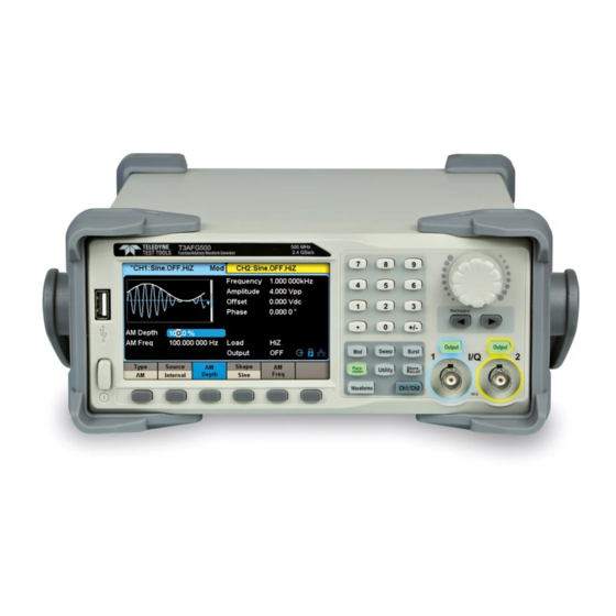
Teledyne T3AFG Series User Manual
Function/arbitrary waveform generator
Hide thumbs
Also See for T3AFG Series
:
User manual
(170 pages)
1
2
3
4
5
6
Table Of Contents
7
8
9
10
11
12
13
14
15
16
17
18
19
20
21
22
23
24
25
26
27
28
29
30
31
32
33
34
35
36
37
38
39
40
41
42
43
44
45
46
47
48
49
50
51
52
53
54
55
56
57
58
59
60
61
62
63
64
65
66
67
68
69
70
71
72
73
74
75
76
77
78
79
80
81
82
83
84
85
86
87
88
89
90
91
92
93
94
95
96
97
98
99
100
101
102
103
104
105
106
107
108
109
110
111
112
113
114
115
116
117
118
119
120
121
122
123
124
125
126
127
128
129
130
131
132
133
134
135
136
137
138
139
140
141
142
143
144
145
146
147
148
149
150
151
152
153
154
155
156
157
158
159
160
161
162
163
164
165
166
167
168
169
170
171
172
173
174
175
176
177
178
179
180
181
182
183
184
185
186
187
188
189
190
191
192
193
194
page
of
194
Go
/
194
Contents
Table of Contents
Troubleshooting
Bookmarks
Table of Contents
Table of Contents
Quick Start
Handle Adjustment
The Front/Rear Panel
To Select a Waveform
To Set Modulation/Sweep/Burst
To Turn On/Off Output
To Use Numeric Input
To Use Common Function Keys
Front Panel Operations
To Set Sine Waveform
To Set Square Waveform
To Set Ramp Waveform
To Set Pulse Waveform
To Set Noise Waveform
To Set DC Waveform
To Set Arbitrary Waveform
To Set Pseudo Random Binary Sequence (PRBS)
To Set Harmonic Function
To Set IQ Waveform (Optional)
Front Panel IQ Control
Easyiq Software
To Set Modulation Functions
Dsb-Am
Fsk
Ask
Psk
Pwm
To Set Sweep Function
To Set Burst Function
To Store and Recall
Storage System
File Type
File Operation
To Set Utility Function
System Settings
Test Cal
Frequency Counter
Output
Copy/Coupling
Remote Interface
Sync Output
Clock Source
Phase Mode
Overvoltage Protection
Multi-Device Synchronisation
Examples
Example 1: Generate a Sine Waveform
Example 2: Generate a Square Waveform
Example 3: Generate a Ramp Waveform
Example 4: Generate a Pulse Waveform
Example 5: Generate a Noise
Example 6: Generate a Pseudo Random Binary Sequence
Example 7: Generate a Linear Sweep Waveform
Example 8: Generate a Burst Waveform
Example 9: Generate an am Modulation Waveform
Example 10: Generate a FM Modulation Waveform
Example 11: Generate a PM Modulation Waveform
Example 12: Generate a FSK Modulation Waveform
Example 13: Generate an ASK Modulation Waveform
Example 14: Generate a PSK Modulation Waveform
Example 15: Generate a PWM Modulation Waveform
Example 16: Generate a DSB-AM Modulation Waveform
Example 17: Generate an IQ Waveform
Troubleshooting
General Inspection
Troubleshooting
Service and Support
Maintenance Summary
Contact Teledyne Test Tools
Appendix
Appendix A: Accessories
Appendix B: Daily Maintenance and Cleaning
Advertisement
Quick Links
Download this manual
User Manual
T3AFG200-350-500 Series Function/Arbitrary
Waveform Generator
Table of
Contents
Previous
Page
Next
Page
1
2
3
4
5
Advertisement
Table of Contents
Troubleshooting
Troubleshooting
188
Troubleshooting
189
Need help?
Do you have a question about the T3AFG Series and is the answer not in the manual?
Ask a question
Questions and answers
Related Manuals for Teledyne T3AFG Series
Portable Generator Teledyne LeCroy T3AFG120 User Manual
Function/arbitrary waveform generator (170 pages)
Portable Generator Teledyne T3AFG5 Quick Start Manual
Function / arbitrary waveform generators (16 pages)
Portable Generator Teledyne T3AFG200 User Manual
Function/arbitrary waveform generator (194 pages)
Portable Generator Teledyne T3AFG350 User Manual
Function/arbitrary waveform generator (194 pages)
Portable Generator Teledyne T3AFG500 User Manual
Function/arbitrary waveform generator (194 pages)
Portable Generator Teledyne SFG-20 Series User Manual
5 &10 mhz arbitrary/ function waveform generators (126 pages)
Portable Generator Teledyne SDG1000 Series User Manual
(130 pages)
This manual is also suitable for:
T3afg200
T3afg350
T3afg500
Table of Contents
Print
Rename the bookmark
Delete bookmark?
Delete from my manuals?
Login
Sign In
OR
Sign in with Facebook
Sign in with Google
Upload manual
Upload from disk
Upload from URL


Need help?
Do you have a question about the T3AFG Series and is the answer not in the manual?
Questions and answers