Table of Contents
Advertisement
Quick Links
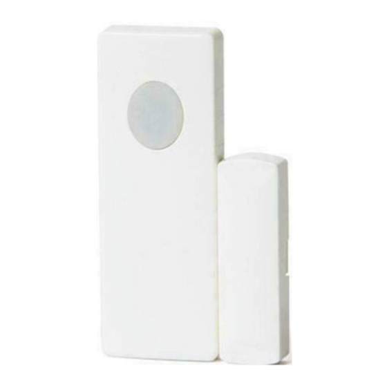
WST-212 Wireless Contact with Local Bypass
Installation Instructions & User Manual
Specifications
Frequency: 345MHz
Battery: One 3Vdc lithium coin cell CR2032 (225 mAh) Operating Humidity: 5-95% RH non condensing
Battery life: 5-8 years
th
Magnet gap: 5/8
inch max
Enrolling
To enroll the sensor, set your panel into program mode, refer to your specific alarm panel manual
for details on these menus. When prompted by the panel, trigger the sensor by moving the
magnet in and out of range of the sensor. The panel will beep when you have successfully learned
in a sensor.
Bypass Enable/Disable
The local bypass feature is disabled by default. To enable this feature, press and hold the button
while inserting the battery. Keep holding down the button until you see two distinct flashes of
light from the red LED. Release the button. The two flashes indicate the bypass feature is enabled
and will remain enabled even if the battery is removed.
To disable the bypass feature press and hold down the button again while the battery is being
inserted. Keep holding down the button until you see the LED illuminate for one second.
Bypass Operation
The local bypass feature enables you to open a protected door or window without sending a
signal to the security panel. To bypass the sensor, the door or window being protected must be in
the closed position. Press and hold the bypass button until the LED starts to flash quickly, then
you may open the door or window. You have 10 seconds to open the door or window before the
LED stops flashing after which the sensor will go back to its normal operation.
When bypass mode has been successfully activated (flashing LED) and the door or window has
been opened, the LED will flash once every 10 seconds to remind you that the sensor is in bypass
mode. The sensor remains bypassed until the door or window is closed. Simply close the door or
window to return your security system to its normal "armed and ready" state after the bypass
feature has been used.
Mounting
Included with the contact is double sided tape for the contact and the magnet. For reliable
bonding ensure the surface is clean and dry. Apply the tape to the sensor and then to the desired
location. Apply firm pressure for several seconds. It is not recommended to mount the tape at
temperatures below 50°F, although after 24 hours the bond will hold at low temperatures. One
side of the sensor is marked with 3 lines; this indicates the location of the reed switch. The
magnet should be mounted facing this side of the sensor, and it must be no further than 5/8 of an
inch from the sensor.
Interchangeable Cover Feature
The contact comes from the factory assembled with a white cover, but included are optional
brown covers as well as covers that completely conceals the bypass switch. To change the cover,
slide the front cover to disengage it from the sensor then remove. Replace with the desired cover
ensuring the Top (as marked on the inside of the cover) points away from the battery. You should
hear a click when the cover engages and disengages from the sensor. You do not need to replace
the back plastic because once mounted the back is not visible. To replace the magnet cover you
will need to gently pry the white cover off with a flat head screw driver and snap the brown cover
in place.
Operating Temperature: 32°-120°F (0°-49°C)
Compatible with Honeywell receivers
Supervisory signal interval: 60 min(approx.)
Advertisement
Table of Contents

Related Manuals for Ecolink WST-212


Summary of Contents for Ecolink WST-212
- Page 1 WST-212 Wireless Contact with Local Bypass Installation Instructions & User Manual Specifications Frequency: 345MHz Operating Temperature: 32°-120°F (0°-49°C) Battery: One 3Vdc lithium coin cell CR2032 (225 mAh) Operating Humidity: 5-95% RH non condensing Battery life: 5-8 years Compatible with Honeywell receivers...
- Page 2 Warranty Ecolink Intelligent Technology Inc. warrants that for a period of 2 years from the date of purchase that this product is free from defects in material and workmanship. This warranty does not apply to damage caused by shipping or handling, or damage caused by accident, abuse, misuse, misapplication, ordinary wear, improper maintenance, failure to follow instructions or as a result of any unauthorized modifications.
Need help?
Do you have a question about the WST-212 and is the answer not in the manual?
Questions and answers