Sign In
Upload
Download
Table of Contents
Contents
Add to my manuals
Delete from my manuals
Share
URL of this page:
HTML Link:
Bookmark this page
Add
Manual will be automatically added to "My Manuals"
Print this page
×
Bookmark added
×
Added to my manuals
Manuals
Brands
Acer Manuals
Desktop
Aspire T310
Service manual
Acer Aspire T310 Service Manual
Hide thumbs
Also See for Aspire T310
:
User manual
(28 pages)
1
2
3
4
5
6
7
8
9
10
11
Table Of Contents
12
13
14
15
16
17
18
19
20
21
22
23
24
25
26
27
28
29
30
31
32
33
34
35
36
37
38
39
40
41
42
43
44
45
46
47
48
49
50
51
52
53
54
55
56
57
58
59
60
61
62
63
64
65
66
67
68
69
70
71
72
73
74
75
76
77
78
79
80
81
82
83
84
85
86
87
88
89
90
91
92
93
94
95
96
97
98
99
100
101
102
103
104
105
106
107
108
109
110
111
112
113
page
of
113
Go
/
113
Contents
Table of Contents
Troubleshooting
Bookmarks
Table of Contents
Revision History
Table of Contents
Chapter 1 System Specifications
Overview
System Specifications
Features & Specification
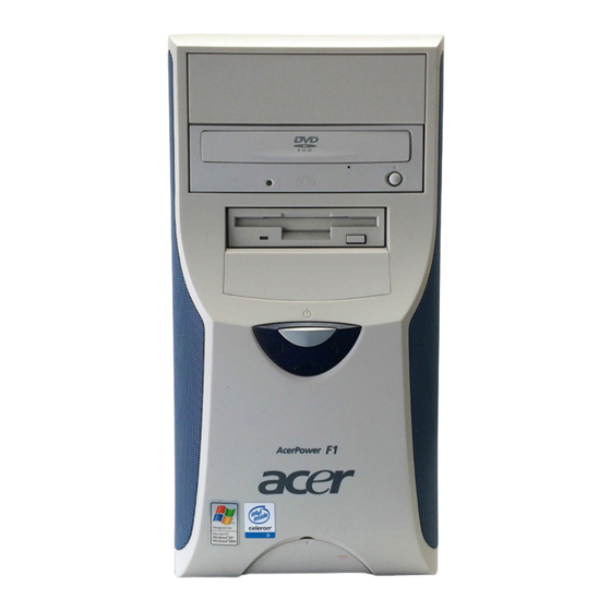
Acer Power F1 Front Panel
Acer Power F1 Rear Panel
Aspire T310/Acer Power F1 Front Panel
Hardware Specifications and Configurations
Power Management Function (ACPI Support Function)
Chapter 2 System Utilities
Entering Setup
Product Information
Standard CMOS Features
Advanced BIOS Features
Advanced Chipset Features
Onchip Agp Control
Integrated Peripherals
Sis Onchip Pci Device
Power Management Setup
Pnp/Pci Configuration
PC Health Status
Frequency/Voltage Control
Load Fail-Safe Defaults
Load Default Settings
Set Supervisor/User Password
Save and Exit Setup
Exit Without Saving
System Utilities
Chapter 3 Machine Disassembly and Replacement
General Information
Before You Begin
Standard Disassembly Procedure
Opening the System
Removing the Front Panel
Removing the Cables
Removing the Modem Card,CD-Rom,Floppy and HDD
Removing the Power Supply
Removing the Heatsink and the CPU
Removing the Memory
Removing the Mainboard
Removing the Power Button
Removing the LED Module
Removing the Daughter Board
Standard Reassembly Procedure
Installing the Daughter Board
Installing the LED Module
Installing the Power Button
Installing the Mainboard
Installing the Heatsink and the CPU
Installing the Memory
Installing the Power Supply
Installing the Modem Card,CD-ROM, Floppy and HDD
Installing the Cables
Installing the Front Panel
Closing System
Chapter 4 Troubleshooting
Power-On Self-Test (POST)
Post Check Points
POST Error Messages List
Error Symptoms List
Troubleshooting
Chapter 5 Jumper and Connector Information
Checking Jumper Settings
Setting Jumpers
Checking Jumper Settings
Connecting Case Components
Front Panel Connector
Connecting Optional Devices
Chapter 6 FRU (Field Replaceable Unit) List
Appendix A Model Definition and Configuration
Appendix B Test Compatible Components
Microsoft Winxp Home Environment Test
Appendix C Online Support Information
Advertisement
Quick Links
1
System Specifications
2
Features & Specification
3
Acer Power F1 Front Panel
4
Hardware Specifications and Configurations
Download this manual
See also:
User Manual
AcerPower F1/Aspire T310
Service Guide
Service guide files and updates are available
on the AIPG/CSD web; for more information,
please refer to
http://csd.acer.com.tw
PRINTED IN TAIWAN
Table of
Contents
Previous
Page
Next
Page
1
2
3
4
5
Advertisement
Table of Contents
Need help?
Do you have a question about the Aspire T310 and is the answer not in the manual?
Ask a question
Questions and answers
Related Manuals for Acer Aspire T310
Desktop Acer Aspire T310 User Manual
(28 pages)
Desktop Acer AcerPower F1 User Manual
Acer acerpower f1 user's manual (24 pages)
Desktop Acer AcerPower F1 User Manual
Acer acerpower f1: user guide (23 pages)
Desktop Acer Aspire 1602M User Manual
Acersystem personal computer (764 pages)
Desktop Acer AcerPower F2 User Manual
Acer desktop pc user's guide (28 pages)
Desktop Acer Power F2 Guía Del Usuario
(20 pages)
Desktop Acer Aspire T320 Manuel D'utilisation
(20 pages)
Desktop Acer Aspire T320 Service Manual
(102 pages)
Desktop Acer Aspire T330 User Manual
Acer desktop pc user's guide (21 pages)
Desktop Acer Aspire T300 Guia Do Usuário
(20 pages)
Desktop Acer Aspire T300 User Manual
Acer aspire t300: user guide (17 pages)
Desktop Acer Aspire T300 Guía Del Usuario
(20 pages)
Desktop Acer Aspire T300 Manuel D'utilisation
(20 pages)
Desktop Acer Aspire T300 Service Manual
(75 pages)
Desktop Acer Aspire G3-605 User Manual
User manual (28 pages)
Desktop Acer Aspire Z3-105 User Manual
User manual (windows 8.1) (63 pages)
This manual is also suitable for:
Acerpower f1
Power f1b
Table of Contents
Print
Rename the bookmark
Delete bookmark?
Delete from my manuals?
Login
Sign In
OR
Sign in with Facebook
Sign in with Google
Upload manual
Upload from disk
Upload from URL


Need help?
Do you have a question about the Aspire T310 and is the answer not in the manual?
Questions and answers