
Related Manuals for Samsung C100R-5


Summary of Contents for Samsung C100R-5
-
Page 1: Table Of Contents
MICROWAVE OVEN C100R-5 C100R-5(SILVER) Manual MICROWAVE OVEN CONTENTS 1. Precaution 2. Specifications 3. Operating Instructions 4. Disassembly and Reassembly 5. Alignment and Adjustments 6. Troubleshooting 7. Exploded Views and Parts List 8. PCB Diagrams 9. Schematic Diagrams... - Page 2 ELECTRONICS This Service Manual is a property of Samsung Electronics Co.,Ltd. ©Samsung Electronics Co., Ltd. November 2003 Any unauthorized use of Manual can be punished under applicable Printed in Korea International and/or domestic law. Code No. : DE68-03334A...
- Page 3 PRECAUTIONS TO BE OBSERVED BEFORE AND DURING SERVICING TO AVOID POSSIBLE EXPOSURE TO EXCESSIVE MICROWAVE ENERGY (a) Do not operate or allow the oven to be (c) Before turning on microwave power operated with the door open. for any service test or inspection within (b) Make the following safety checks on the microwave generating all ovens to be serviced before activating...
-
Page 4: Precaution
1. Precaution Follow these special safety precautions. Although the microwave oven is completely safe during ordinary use, repair work can be extremely hazardous due to possible exposure to microwave radiation, as well as potentially lethal high voltages and currents. 1-1 Safety precautions ( 11. - Page 5 1-2 Special Servicing Precautions (Continued) 17. When checking the continuity of the witches or transformer, always make sure that the power is OFF, and one of the lead wires is disconnected. 18. Components that are critical for safety are indicated in the circuit diagram by shading, or .
-
Page 6: Specifications
2. Specifications 2-1 Table of Specifications TIMER 99 MINUTES POWER SOURCE 230V 50Hz, AC POWER CONSUMPTION MICROWAVE : 1,400W GRILL : 1,300W CONVECTION : 1,700W OUTPUT POWER FROM 100 TO 900W(6 LEVEL POWER) (IEC-705 TEST PROCEDURE) OPERATING FREQUENCY 2,450MHz MAGNETRON OM75P(31)ERHN COOLING METHOD COOLING FAN MOTOR... -
Page 7: Operating Instructions
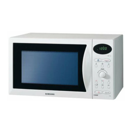
3. Operating Instructions 3-1 Control Panel 3-2 Features & External Views Door Ventilation Holes Light Safety Interlock Holes Control Panel Guide Roller Glass Plate Door Latches Coupler Grill Rack 216mm 369mm 517mm 511mm... -
Page 8: Disassembly And Reassembly
4. Disassembly and Reassembly 4-1 Replacement of Magnetron, Motor Assembly and Lamp Remove the magnetron including the shield case, permanent magnet, choke coils and capacitors (all of which are contained in one assembly). 1. Disconnect all lead wires from the magnetron and lamp. - Page 9 4-3 Replacement of Door Assembly 4-3-4 Removal of Key Door &Spring 4-3-1 Removal of Door Assembly Remove pin hinge from Door "E" securing the upper hinge and lower hinge. The remove door assembly. Datach spring from Door "E" and key door. 4-3-2 Removal of Door "C"...
- Page 10 4-3-6 Reassembly Test After replacement of defective component parts of the door, reassemble it and follow the instructions below for proper installation and adjustment so as to prevent an excessive microwave leakage. 1. When mounting the door to the oven, be sure to adjust the door parallel to the bottom line of the oven face plate by moving the upper hinge and lower hinge in the direction necessary for proper alignment.
- Page 11 4-6 Replacement of Control Circuit Board 1. Be sure to disclyarge any static electricity from your body, and avoid touching the "touch control" circuitry. 2. Disconnect the connectors from the control circuit board. 3. Remove screws securing the control box assembly.
-
Page 12: Alignment And Adjustments
5. Alignment and Adjustments PRECAUTION 1. High voltage is present at the high voltage terminals during any cook cycle. 2. It is neither necessary nor advisable to attempt measurement of the high voltage. 3. Before touching any oven components or wiring, always unplug the oven from its power source and discharge the high voltage capacitor. - Page 13 5-4 High Voltage Capacitor 1. Check continuity of the capacitor with the meter set at the highest resistance scale. 2. Once the capacitor is charged, a normal capacitor shows continuity for a short time, and then indicates 9M . 3. A shorted capacitor will show continuous continuity. 4.
- Page 14 5-8 Output Power of Magnetron CAUTION MICROWAVE RADIATION PERSONNEL SHOULD NOT ALLOW EXPOSURE TO MICROWAVE RADIATION FROM MICROWAVE GENERATOR OR OTHER PARTS CONDUCTING MICROWAVE ENERGY. The output power of the magnetron can be measured by performing a water temperature rise test. Equipment needed : * Two 1-liter cylindrical borosilicate glass vessel (Outside diameter 190 mm) * One glass thermometer with mercury column...
- Page 15 5-9 Procedure for Measurement of Microwave Energy Leakage 1) Pour 275±15cc of 20±5° C(68±9° F) water in a beaker which is graduated to 600cc, and place the beaker in the center of the oven. 2) Start to operate the oven and measure the leakage by using a microwave energy survey meter.
-
Page 16: Troubleshooting
6. Troubleshooting PRECAUTION 1. CHECK GROUNDING BEFORE CHECKING FOR TROUBLE. 2. BE CAREFUL OF THE HIGH VOLTAGE CIRCUIT. 3. DISCHARGE THE HIGH VOLTAGE CAPACITOR. 4. WHEN CHECKING THE CONTINUITY OF THE SWITCHES OR TRANSFORMER, DISCONNECT ONE LEAD WIRE FROM THESE PARTS AND THEN CHECK CONTINUITY WITHOUT THE POWER SOURCE ON. - Page 17 6-1 Electrical Maltunction(continved) SYMPTOM CAUSE CORRECTIONS Oven lamp and fan motor turn on 1. Misadjustment or loose wiring Adjust door and latch switches. of primary latch switch 2. Defective primary latch switch Oven can program but timer 1. Open or loose wiring of does not start.
-
Page 18: Exploded Views And Parts List
7. Exploded Views and Parts List 7-1 Exploded Views H016 M001 W006 M005 W003 M013 M095 M113 M008 M010 M015 M011 M016 M053 W002 M057 M019 M009 M031 M004 M017 M012 M054 M023 M029 M036 M035 M051 T001 B018 M049 M037 B006 T017... - Page 19 7-2 Main Parts List Code No. Description Specification Q'ty Remark B001 3405-001034 SWITCH-MICRO 125/250VAC,16A,200GF,SPST-N B002 3405-001032 SWITCH-MICRO 125/250VAC,16A,200GF,SPDT B006 DE66-40021B LATCH-BODY -,-,-,M959/XSA,-,-,- B009 DE66-90054B LEVER-SWITCH NYLON#66(2021SW),40G,M959/X SENSOR B018 DE93-20020D ASSY BODY LATCH M959/XSA,-,-,-,- HEATER M001 DE64-01161A PANEL-OUTER 5th. 1.0 Convection,SECC,T0. WHITE M001 DE64-01161B...
- Page 20 7-3 Door Parts List D049 D009 D047 D006 D024 D002 D010 D007 D011 D043 D021 Code No. Description Specification Q'ty Remark D002 DE64-40319A DOOR-A CK95,PC,-,-,-,-,WHT,- WHITE D002 DE64-40319H DOOR-A C100-SL,PC,-,-,-,-,SILVER,- SILVER D006 DE64-40012C DOOR-C CK95,PBT,-,-,-,-,BLK,- D007 DE61-00199A SPRING-KEY M1977,HSWR,D6,-,-,25 1/4,25 1 D009 DE61-80002A HINGE-UPPER...
- Page 21 7-4 Control Parts List C002 C003 C005 C071 C009 C043 C045 C011 C012 C025 C041 C082 Code No. Description Specification Q'ty Remark C002 DE94-00647B ASSY CONTROL-PANEL -,C100-R/BWT,-,RUSSIA WHITE C002 DE94-00647T ASSY CONTROL-PANEL -,C100R-5SL/BWT,PC/SILVER,5TH. SILVER C003 RCS-C100-04 ASSY PCB PARTS C100-5/XEE,230V50HZ C005 DE64-00369B CONTROL-PANEL...
- Page 22 7-5 Casing Parts List H001 H003 H002 H004 H005 H002 H006 H007 H008 H011 Code No. Description Specification Q'ty Remark H001 DE31-10171A MOTOR CONVECTION SMC-105EA,230V/50HZ,280 H002 DE31-90019A BLADE-FAN SECC,T0.6,-,-,-,-,- H002 DE31-90020A BLADE-FAN ALSTAR,T0.6,W250,L250,-,-,- H003 DE47-70077A HEATER-CONVECTION SHC-118E1,-,-,1680W,-, H005 DE97-00472A ASSY-COVER CASING -,5th.
- Page 23 7-6 Standard Parts List Code No. Description Specification Q'ty Remark DE67-20185C SCREEN-DOOR CK95/CK99,-,T2.0,W317.5,L198,-,-,- DE67-20184K SCREEN-DOOR(B) -,CK920T,TEMP GLASS,T3.2,W376.7, 6006-001171 SCREW-ASSY MACH WS,PH,+,M4,L8,NI PLT B-EARTH 6006-001170 SCREW-ASSY TAPP WS,TH,+,M4,L10,ZPC(YEL) A-N-FILTER 6006-001170 SCREW-ASSY TAPP WS,TH,+,M4,L10,ZPC(YEL) A-P-CORD 6006-001170 SCREW-ASSY TAPP WS,TH,+,M4,L10,ZPC(YEL) B-PLATE 6006-001170 SCREW-ASSY TAPP WS,TH,+,M4,L10,ZPC(YEL) C-B-EARTH 6006-001174...
- Page 24 8. P.C.B Diagrams 8-1 P.C.B Diagrams (This Document can not be used without Samsung's authorization)
- Page 25 8-2 P.C.B Parts List Code No. Description Specification Q'ty Remark 3501-001062 RELAY-POWER 24VDC,523.2MW,16000MA,1FORMA,15MS,10MS RY02 3501-001068 RELAY-POWER 24VDC,523MW,16000MA,1FORMA,15MS,10MS RY04,05 3501-001155 RELAY-MINIATURE 24VDC,200MW,3000MA,1FORMA,10MS,10MS RY01,03,06,07 3601-001126 FUSE-CARTRIDGE 250V,1.6A,FAST-ACTING,CERAMIC,5x20mm FUSE DE07-00031B LED DISPLAY CSE-4258ESM1,C130,-,56SEG,8DIGIT,57.8*28.8*22 LED1 DE09-00378A IC MICOM TMP87CH47U-5CD6,C100 - 5/XEF,44PIN,+5V,8MHz, IC01 DE26-00078A TRANS L.V SLV-C100,230V,50HZ,AC17.0V/6.8V,NO-FUSE, LVT1 DE30-20016A...
-
Page 26: Schematic Diagrams
9. Schematic Diagrams 9-1 Schematic Diagrams (This Document can not be used without Samsung's authorization) MAGNETRON HIGH VOLTAGE DIODE TO CHASSIS HIGH VOLTAGE CAPACITOR H.V.FUSE SYMBOL COLOR BROWN BLACK BLUE HIGH VOLTAGE TRANSFORMER...
Need help?
Do you have a question about the C100R-5 and is the answer not in the manual?
Questions and answers