
Related Manuals for Samsung C100R-5D


Summary of Contents for Samsung C100R-5D
- Page 1 BASIC: C100R-5U/BWT MODEL: C100R-5D MODEL CODE: C100R-5D/BWT 1. 1.0 cu.ft convection 2. LED - Bar...
-
Page 2: Table Of Contents
• Contents 1. Precaution ................... . 3 1-1 Safety precautions . -
Page 3: Precaution
1. Precaution... -
Page 4: Safety Precautions
1. Precaution Follow these special safety precautions. Although the microwave oven is completely safe during ordinary use, repair work can be extremely hazardous due to possible exposure to microwave radiation, as well as potentially lethal high voltages and currents. 1-1 Safety precautions ( All repairs should be done in accordance with the 13. -
Page 5: Special High Voltage Precautions
1. Precaution 1-2 Special High Voltage Precautions High Voltage Warning Do not attempt to measure any of the high voltages --this includes the filament voltage H. V. Capacitor of the magnetron. High voltage is present during any cook cycle. Before touching any components or wiring, always unplug the oven and discharge the high voltage capacitor (See Figure 1-1) The high-voltage capacitor remains charged about... -
Page 6: Specifications
2. Specifications 2-1 Table of Specifications Model Items Sub Items C100R-5D C100R-5U Power source 230 V ~ 50 Hz AC 230 V ~ 50 Hz AC Maximum Power 3100 W 3100 W Microwave 1400 W 1400 W Power comsumption Grill... -
Page 7: Accessory
2. Specifications 2-2 Accessory Item Description Code No. Q’ty Coupler DE67-00182A ASSY-GUIDE ROLLER DE97-00222A TRAY-COOKING DE74-20015G ASSY-WIRE RACK DE97-00216E ASSY-WIRE RACK DE97-00136B... -
Page 8: Operating Instructions
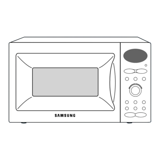
3. Operating Instructions 3-1 Control Panel 1. Display 10. Clock setting 2. Auto defrost feature selection 11. Auto reheat & Cook feature selection 3. Standing time setting 12. Cooking time adjustment 4. Memory cook feature selection 13. Microwave / Power level mode selection 5. -
Page 9: Features & External Views
3. Operating Instructions 3-2 Features & External Views Door Ventilation Holes Light Safety Interlock Holes Control Pane Guide Roller Glass Plate Door Latches Coupler Grill Rack 346mm 336mm 517mm 511mm... -
Page 10: Disassembly And Reassembly
4. Disassembly and Reassembly 4-1 Replacement of Magnetron, Motor Assembly and Lamp Remove the magnetron including the shield case, permanent magnet, choke coils and capacitors (all of which are contained in one assembly). Disconnect all lead wires from the magnetron and lamp. Remove a screw securing air cover. -
Page 11: Replacement Of Door Assembly
Screws 4. Disassembly and Reassembly Low Hinge Low Hinge 4-3 Replacement of Door Assembly Screws Key Door Spring Screws 4-3-1 Removal of Door Assembly 4-3-2 Removal of Door “C” Securing the upper hinge and lower hinge. Insert flat screwdriver into the gap between Door “A” and Door “C”... -
Page 12: Reassembly Test
4. Disassembly and Reassembly 4-3 Replacement of Door Assembly (Continued) 4-3-6 Reassembly Test After replacement of the defective component parts of the door, reassemble it and follow the instructions below for proper installation and adjustment so as to prevent an excessive microwave leakage. -
Page 13: Replacement Of Control Circuit Board
4. Disassembly and Reassembly 4-6 Replacement of Control Circuit Board Be sure to dislyarge any static electricity from your body, and avoid touching the “touch control” circuitry Disconnect the connectors from the control circuit board. Remove screws securing the control box assembly. Lift up the control circuit board from right side and remove the hooks holding the control circuit board to box assembly SCREWS... -
Page 14: Alignment And Adjustments
5. Alignment and Adjustments 1. High voltage is present at the high voltage terminals during any cook cycle. 2. It is neither necessary nor advisable to attempt measurement of the high voltage. 3. Before touching any oven components or wiring, always unplug the oven from its power source and discharge the high voltage capacitor. -
Page 15: High Voltage Capacitor
5. Alignment and Adjustments 5-4 High Voltage Capacitor Check continuity of the capacitor with the meter set at the highest resistance scale. Once the capacitor is charged, a normal capacitor shows continuity for a short time, and then indicates 9MΩ. A shorted capacitor will show continuous continuity. -
Page 16: Output Power Of Magnetron
5. Alignment and Adjustments 5-8 Output Power of Magnetron MICROWAVE RADIATION PERSONNEL SHOULD NOT ALLOW EXPOSURE TO MICROWAVE RADIATION FROM MICROWAVE GENERATOR OR OTHER PARTS CONDUCTING MICROWAVE ENERGY. The output power of the magnetron can be measured by performing a water temperature rise test. Equipment needed : •... -
Page 17: Procedure For Measurement Of Microwave Energy Leakage
5. Alignment and Adjustments 5-9 Procedure for Measurement of Microwave Energy Leakage Pour 275±15cc of 20±5°C(68±9°F) water in a beaker which is graduated to 600cc, and place the beaker in the center of the oven. Start to operate the oven and measure the leakage by using a microwave energy survey meter. -
Page 18: Troubleshooting
6. Troubleshooting WARNING FOR HIGH VOLTAGE 4000 VOLTS EXIST AT THE HIGH VOLTAGE AREA. DO NOT OPERATE THE OVEN WITH CABINET PARTS REMOVED. DO NOT REMOVE THE CABINET PARTS IF THE POWER SUPPLY CORD IS PLUGGED IN THE WALL OUTLET. UNPLUG THE POWER CORD BEFORE SERVICING. 6-1 Electrical Malfunction Parts Cause... - Page 19 6. Troubleshooting part Cause Diagnosis Remedy If a small amount of food is heated for a To increase the oven 1) Too small a load long time, period of microwave may turn water into water into the off during operation. oven.
- Page 20 6. Troubleshooting Oven does not operate. *Inspection method Make sure to inspect the power relay after replacing primary Is Primary interlock switch, secondary interlock Is Fuse OK? interlock switch switch and door sensing switch. normal? Primary interlock switch Secondary interlock switch Door sensing switch *Latch switch assembly Is Power Relay...
- Page 21 6. Troubleshooting Buttons of the control panel do not work. *Inspection method buttons pressed Refer to User Manual in the correct order? Tact Type Switch (Tact Switch) Is the Button connector of the control panel normal? Replace PCB. Connector Membrane Type Membrane Switch Connector...
-
Page 22: Unsatisfactory Cooking
6. Troubleshooting 6-2 Unsatisfactory Cooking Parts Cause Diagnosis Remedy 1) Open cathode Check the terminals with a multimeter to see Replace magnetron. of magnetron if the heater circuit is open. Check the H. V. Diode for continuity in the reverse and normal directions using meter. If 2) Defective H. -
Page 23: Exploded Views And Parts List
7. Exploded Views and Parts List 7-1 Exploded Views M001 W003 M005 P186 W006 M013 M095 M113 M008 M010 M011 M015 M053 M058 H008 M012 M019 W002 M054 P109 H013 M023 T030 H018 M036 T026 T026 T030 M051 B006 T010 T009 M038 M049... -
Page 24: Main Parts List
7. Exploded Views and Parts List 7-2 Main Parts List (S.N.A : SERVICE NOT AVAILABLE) Level Code No. Description Specification Q’ty SA/SNA Remark M041 0402-001554 DIODE-RECTIFIER HV03-12T01,12000V,0.4A,D P--B/PLATE M039 2501-001015 C-OIL 1.0uF,2100V,BK,35X54X80,20mm P--B/PLATE M019 3601-001197 FUSE-CARTRIDGE 250V,15A,SLOW-BLOW,CERAMI P--N/F M036 4713-001046 LAMP-INCANDESCENT 240V,104mA,25W,ORG,-,- M--CV/AIR... - Page 25 7. Exploded Views and Parts List 7-2 Main Parts List (Continued) (S.N.A : SERVICE NOT AVAILABLE) Level Code No. Description Specification Q’ty SA/SNA Remark W006 DE39-40409A WIRE HARNESS-E 230V50HZ,M9G45,CTW,-,-,- M011 DE61-50347A BRACKET-EARTH -,BSS2-A,T1.0,W35,L43,MBGF T001 DE74-20015G TRAY-COOKING 3RD-1.0,T6,1115G,HKS,-,-,-, T032 DE97-00216E ASSY-WIRE RACK C100,HIGH-RACK/LOW-RACKAS T009 DE97-00136B...
-
Page 26: Door Parts List
7. Exploded Views and Parts List 7-3 Door Parts List D049 D009 D047 D006 D024 D002 D010 D007 D011 D021 (S.N.A : SERVICE NOT AVAILABLE) Level Code No. Description Specification Q’ty SA/SNA Remark D049 DE94-00644M ASSY DOOR C100-5,WHT,5th. 1.0 Convection D006 DE64-40012C DOOR-C... -
Page 27: Control Parts List
7. Exploded Views and Parts List 7-4 Control Parts List C002 C005 C003 C082 C009 C071 C043 C045 C011 C012 C025 C041 (S.N.A : SERVICE NOT AVAILABLE) Level Code No. Description Specification Q’ty SA/SNA Remark C082 DE94-00646V ASSY CONTROL-BOX -,C100-5R/BWT,PC/WHT,5t C071 DE63-00088A COVER-LED... -
Page 28: Casing Parts List
7. Exploded Views and Parts List 7-5 Casing Parts List H001 H003 H002 H005 H011 Z009 H004 H013 H012 H010 H006 H014 H015 H002 H005 H007 H010 H008 (S.N.A : SERVICE NOT AVAILABLE) Level Code No. Description Specification Q’ty SA/SNA Remark H005 DE97-00472A ASSY-COVER CASING... -
Page 29: Standard Parts List
7. Exploded Views and Parts List 7-6 Standard Parts List (S.N.A : SERVICE NOT AVAILABLE) Level Code No. Description Specification Q’ty SA/SNA Remark 6001-000033 SCREW-MACHINE TH,M4X10,STS304 M--SENSOR 6002-001079 SCREW-TAPPING TH,+,-,2S,M4,L10,PASS,STS3 M--C/CEILING 6002-001320 SCREW-TAPPING TH,+,2S,M4,L8,PASS,STS304, M--B/HEATER 6002-001321 SCREW-TAPPING PWH,+,2S,M5,L10,ZPC(YEL) M--HVT,P--MGT 6002-001325 SCREW-TAPPING TH,TORX,2S,M4,L12,ZPC(YEL) P--P/CORD,M--BKT... -
Page 30: Schematic Diagrams
8. Schematic Diagrams 8. Schematic Diagrams 8-1. Schematic Diagrams (This Document can not be used without Samsung’s authorization) ���� ���� ��� �� ��� �� ���� ��������� ���� ��������... -
Page 31: Electrical Parts List
9. Electrical Parts List 9. Electrical Parts List 9-1. Electrical Parts List (S.N.A : SERVICE NOT AVAILABLE) Level Code No. Description Specification Q’ty SA/SNA Remark RCS-C100-04 ASSY PCB PARTS C100-5/XEE,230V50HZ 3501-001155 RELAY-MINIATURE 24VDC,200MW,3000MA,1FORM RY07,RY06,RY03,RY01 3601-001126 FUSE-CARTRIDGE 250V,1.6A,FAST-ACTING,CER FUSE DE07-00031B LED DISPLAY CSE-4258ESM1,C130,-,56SEG,8D LED1 DE26-00078A TRANS L.V... - Page 32 9. Electrical Parts List (S.N.A : SERVICE NOT AVAILABLE) Level Code No. Description Specification Q’ty SA/SNA Remark 3711-004200 CONNECTOR- BOX,4P/7P,1R,2.5MM,STRA CN01 HEADER DE41-00227A PCB-MAIN RC-C100-**,FR-1,1,-,-,T1.6*W19 DE60-60012A PIN-EYELET ID2.1,OD2.5,L3.0,SN,BSP,T0.25 DE09-00378A IC MICOM TMP87CH47U-5CD6,C100 - 5/ IC01 XEF,4 3501-001188 RELAY-POWER 24V DC,0.53W,-,1FORMA,9.3MS, RY02 3501-001209 RELAY-POWER...
-
Page 33: Wiring Diagrams
10. Wiring Diagrams 10-1 Wiring Diagrams (This Document can not be used without Samsung’s authorization) MAGNETRON HIGH VOLTAGE DIODE TO CHASSIS HIGH VOLTAGE CAPACITOR H.V.FUSE SYMBOL COLOR BROWN BLACK BLUE HIGH VOLTAGE TRANSFORMER... -
Page 34: Reference
11. Reference 11-1 Model name standard Baoad Middle Product Distinguisher Distinguisher Full Nane Code Classification Classfication USA CMO (EPOXY CAVITY) (Counter-top MWO) USA UTC (Under The Cabinet) Browner, Grill USA GRILL Convection USA CONVECTION USA CMO Sensor USA CMO SENSOR DC MWO USA DC MWO Hospital MWO... -
Page 35: Customer Inquiry Cases And Countermeasures
• Close the door completely. => Press the Cancel the oven is out of order. button. => Press the Start button. • Contact the nearest Samsung after-sales service center. • Ground problem may • If the oven is placed in a humid area, buy an electric happen when the oven wire in a store selling electrical products. - Page 36 Refer to the section of ERROR in User Manual. Error with Failure and Non- failure. • Visit the nearest Samsung Service Center or local dealer to buy accessories. Before visiting, check the model name printed on the lower right side of the front Accessory panel of the oven.
- Page 37 © Samsung Electronics Co., Ltd. June 2006 Printed in Korea Code No. : DE68-04131A...
Need help?
Do you have a question about the C100R-5D and is the answer not in the manual?
Questions and answers