
Subscribe to Our Youtube Channel
Related Manuals for Magnimage MIG-CL9600 Series


Summary of Contents for Magnimage MIG-CL9600 Series
- Page 1 MIG-CL9600series User manual V1.0 △ Before using this Video Wall Controller,please read this manual carefully and preserved for reference in the future. Video Wall controller...
- Page 2 Statements Without the written permission, any unit or individual could not copy, reproduction or translate the book or part of it. Also could not transmit it in any form or any way(electronic,mechanical, photocopying, record or other way) for any business and profitable purpose.
-
Page 3: Table Of Contents
System menu ......................19 Status Icons ..............................20 Menu browsing ............................20 Main menu ............................. 21 Status information ......................... 22 Function setting ..........................23 Communication setting ......................... 24 Language ............................25 About Magnimage......................... 26 Software ......................... 27 Operating environment ..........................27... - Page 4 Installation ............................. 28 Unloading ............................30 Running software ............................31 Connection window ........................32 Main Program Window......................... 34 Guide Window..........................40 Software Using ............................42 Preparation ............................. 42 New Project ........................... 44 Save Project ........................... 50 Open Project ..........................51 Deepen Understanding........................
-
Page 5: Briefs
Briefs Thanks for your purchasing our Video wall Controller. Do hope you can enjoy the experience of the product performance. The design of the Video wall Controller conforms to international and industry standards. But if with improper operation, there will be a personal injury and property damage. In order to avoid the dangerous, please obey the relevant instructions when you install and operate the product. -
Page 6: Feature
Feature The pure hardware architecture, full channel RGB 24bit/60HZ Support DP and HDMI 4K * 2K/60Hz input, and DP support 8K*1K/60Hz Support adjusting the size and position of display layer, full screen roaming Input - output signal real-time monitoring image (IP Replay function) ... -
Page 7: Safety Notice
Safety Notice The power input voltage for this product is 100-240VAC50/60Hz, please use the correct power supply When you need to connect or plug out any signal or control line, please confirm all the power line have been plugged out ... -
Page 8: Function Introduction
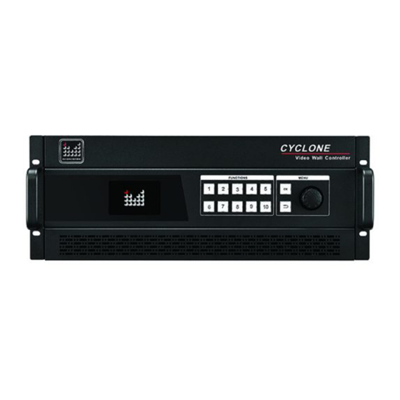
Function introduction Summary CYCLONE video wall controller is an video processing equipment of pure hardware architecture, mainly be applied in LED large screen with small pixel spacing, realize multi displays seamless splicing and running multi window, it can apply in security monitoring, administration, military command, exhibition display, education and scientific research and other industries. -
Page 9: Technical Specifications
technical specifications Input signal specification Interface Number Specifications VESA standard , VESA standard support EDID HDMI HDMI-1.3standard 480i、576i、720p、1080i/p(3G SDI) DP 1.1 standard 3840× 1080× 60 Hz, support EDID management(MIG-9614 not available) HDMI(4K)+ HDMI2.0, DP1.2, 3840*2160/60Hz, DP(4K) support EDID management(MIG-9614 not available) H.264 Output signal specification Interface... - Page 10 Electrical specifications Input power 100~240VAC,50/60Hz working temperature 0~45℃ working temperature 10% -90% non-condensing For boards type and specification please refer to the board introduction chapter...
-
Page 11: Front And Rear Panel Of Video Wall Controller
Front and rear panel of Video Wall controller MIG-CL9604Front panel 1、 LOGO Magnimage 2、 LCD display Mainly used for showing the status of the device, including the input and output board configuration, firmware version, ambient temperature, network configuration and other information 3、... -
Page 12: Mig-Cl9604Rear Panel
MIG-CL9604Rear Panel 1、 Board slot MIG-CL9600 has a total of 12 board slots, in the back of the case, it has 1 to 12 of the numerical identification 2、 Dust-against bracket The dust-against bracket can be disassembled conveniently for replacing a new one. 3、... - Page 13 MIG-CL9604-B Input configuration 6 input board slots (3rd to 8th slots), area(the dark area) Output configuration 6 output board slot (1 , 2rd, and 9 to 12th slot), each area(the light area) board slot supports the main output, Only 11 and 12 slot can support multi images preview output network IP...
-
Page 14: Mig-Cl9614Front Panel
MIG-CL9614Front panel 1、 LOGO Magnimage 2、 LCD display Mainly used for showing the status of the device, including the input and output board configuration, firmware version, ambient temperature, network configuration and other information 3、 Functional key Buttons 1~10, for the input of the machine... -
Page 15: Mig-Cl9614 Rear Panel
MIG-CL9614 Rear Panel 1、 Board slot MIG-CL9614 has a total of 39 board slots, among them18 input board slots, 18 output board slots and 1 control board slot. 2、Dust-against bracket The dust-against bracket can be disassembled conveniently for replacing a new one. 3、... - Page 16 Input configuration 18 input board slots area(the dark area) Output configuration 18 output board, all the output slot can support multi area(the light area) images preview output and network IP replay...
-
Page 17: Board Introduction
Board Introduction MIG-CL9600 series of multi videos controller has abundant boards for selection. The control board, as a standard configuration, is the core part of the whole device; input and output boards are matched configuration which can be matched freely according to the actual demand. -
Page 18: Output Board
Output board MIG-CL9000-OUT406DVI: [DVI 4× 1@6Layer Output board] DVI interface 4 DVI individual output mode. Working mode Program output Layer Standard output mode, it supports 6 separate image layers, and a description HD background Output The best output resolution is 1920 x 1080@60Hz, and supports resolution customized output resolution MIG-CL9000-OUT404DVI: [DVI 4×... - Page 19 MIG-CL9000-OUT404SDI: [SDI 4× 1@4Layer Output board]] SDI interface 4 SDI ports are individual output Working mode S Program output Layer Standard output mode, each SDI output port support 4 image description layers, and a HD background Output The best output resolution is 1920 x 1080@60Hz, and supports 1080i/60Hz,720P/60Hz resolution MIG-CL9000-OUTIP: [network IP replay]...
-
Page 20: Input Board
Input board MIG-CL9000-INDVI: [DVI× 4 Input Board] Signal specification Support only VESA standard DVI-D digital signal, support EDID management function Interface description 24+5 pin / head interface MIG-CL9000-INHDMI: [HDMI× 4 Input Board ] Signal specification EIA/CEA-861 standard, HDMI-1.3 standard Interface description HDMI Type A MIG-CL9000-INSDI: [SDI×4 Input Board ] Signal specification... - Page 21 MIG-CL9000-INIP: [IP× 2 Input Board] Signal specification IP Video streaming / H.264 RJ45 × 2 Interface description MIG-CL9000-INVGA: [VGA× 4 Input Board] Signal specification VESA standard Interface description 15pinD-sub / head interface MIG-CL9000-IN2DP: [DP× 2 Input Board] Signal specification DP1.1 standard (3840× 1080/60hz), support EDID Interface description Full Size 20 pin, MIG-9614 not available...
- Page 22 MIG-CL9000-INDP12: [DP× 1,HDMI× 1 Input Board] Signal specification HDMI2.0, DP1.2 standard, support 3840× 2160/60Hz, support EDID management Interface description HDMI Type A and Full Size 20 pins, input ports optional, (MIG-9614 not available) MIG-CL9000-INSDIVGA:[SDI× 2&VGA× 2 input board] Signal specification 2 SDI input, 2 VGA input :...
-
Page 23: System Menu
System menu As shown in the following figure, MIG-CL9600'ssystem menu, it consists of the front panel of the LCD screen, buttons, and the knob, it can real-time view of the operation information of the system LCD screen: colorful LCD screen, used to display all the information menu, as well as the user settings menu Function keys: button 1~10, in the specific menu page, you can complete the user input setting... -
Page 24: Status Icons
Status Icons Icons Names characteristics Temperature The icon is in white, which means the environment state temperature is appropriate; Yellow, the temperature is high; The Red color indicates the temperature is too high. System error When the icon appears, refer that it has an error on the system input and output modules USB Device when USB device is connected to the control panel, it will... -
Page 25: Main Menu
LCD screen display as shown below: Menu Status Info Misc Communication /菜单语言 Language About Magnimage Status Info It can display input and output configuration information; each module firmware version information; environment temperature and fan state; each board current and voltage state Misc Equipment with its LCD screen test;... -
Page 26: Status Information
Status information Status Info Input information Output information Firmware version Temperature & Fans Electric Report Input information Graphical show the input Info directly , green color of the port indicates that the port has been detected in the effective input signal Output information Graphical show the input Info directly Firmware version... -
Page 27: Function Setting
Function setting Misc LCD Test Pattern Factory Reset LCD Test Pattern In the menu, move around knob for selecting test card, OK keys or key can exit the state Factory Reset Make all settings of the machine to initial state of factory, after the operating, you need to restart the power... -
Page 28: Communication Setting
Communication setting Communication MAC:E2:E8:FA:1E:6A:0A IP address 192.168.1.223 Subnet mask 255.255.255.0 Apply settings Cancel Reset IP address In This interface, we use figure keys and OK keys to input the IP address, for example: 1、9、2、1、6、8、1、 OK、2、2、3、OK Subnet mask In This interface , the use of figure keys and OK keys to input the subnet mask, for example: 2、5、5、2、5、5、2、... -
Page 29: Language
Language /菜单语言 Language English 简体中文 繁體中文 English Set menu display language 简体中文 Set menu language in simplified Chinese 繁體中文 Set menu language in traditional Chinese... -
Page 30: About Magnimage
About Magnimage About Magnimage http://www.magnimage.com... -
Page 31: Software
Software MIG Cyclone Multi-display System,MIG-CL9600Host computer software (hereinafter referred to as the PC software), for Cyclone series multi screen display controller is developed for the professional control software. Software interface is intuitive and simple, easy to operate, almost all the functions of the controller, the need to use the PC software to achieve. -
Page 32: Installation
Installation Open the CD attached to the controller, to find "MIG_Cyclone-SetupVX.XXX.msi" file, double-click the file, install it in the new PC which did not install the software, the computer will start to install a boot program.If the PC have been installed in PC software, the computer will start the repair or uninstall program guide. - Page 33 Click the setup program, start the installation process, click "Next"to go to the next step Select the program installation position, and users need to install this program The installation information confirmation, if the previous settings are correct, please click "Next"...
-
Page 34: Unloading
Unloading Click the setup program, start the unloading process, click "Next" to go to the next step At the unloading end, click on "Close"... -
Page 35: Running Software
Running software Open the software, the interface will show above graph, including: 1.Connection window 2.The main program window 3.Guide window... -
Page 36: Connection Window
Connection window Click on the two buttons below the Connection window, it will pop up the menu: 1, network connection A> target IP: the IP address of video wall controller, if the network has multiple devices, it will be displayed on the IP address list, so you can select the target IP wanting to control B>... - Page 37 :123456 Pass word...
-
Page 38: Main Program Window
Main Program Window File Menu Change password New Project Create new project file to store all configuration data and information in current project Open Project Open established project file Save Project Save a project file Load Preset Saved In Load the presets Destination Save Preset To Save the presets... - Page 39 Configuration menu Get Data From Read current configuration data in the devices Destination Set Data To Set current configuration data to the devices Destination Reset To Default Restore host machine to default, restart power after completion Network Display Switch Network Display Board On or Off here, where Board there is tick shows in the left, that means display function is started.
- Page 40 Background Menu Background Selection Enter the background selection interface, view or select the background of each output port Background Settings Enter the background settings interface, view or select the background of each output port Background Display Display current preview of background in the stage of main program area Connection Settings Menu Network...
- Page 41 语言/Language Menu 中文/Chinese The menu will display in Chinese English/英文 The menu will display in English Help Menu About Check current software version of the upper machine...
- Page 42 Stage Stage is the largest area in the window of the entire software, namely the black part of the window, which is used to put all the display screen and input layer. Display screen will be displayed as output rectangular wire-frames in the stage, what in scope of the wire-frames is the corresponding content to be output.
- Page 43 Status Bar Temperature Status Icon stands for thermometer, green or white say in normal range.Yellow or dark golden say on high side.When the temperature increased to a certain degree, the splicing divide will enter a low-power protected mode(abnormal working status). Connecting Status Red says unconnected, green says connected System Status...
-
Page 44: Guide Window
Guide Window Layer Info. Shows the current selected layer information and the layer packet information Output Info. Shows the output port list and the current information of the selected output port Input Info. Shows all the input information of the ports Layer List Shows the layer list including all the information of layer setting Input Scr. - Page 45 Multi-Preview Multi-preview is available when multi-preview cards existed in lower machine. Ethernet Input Ethernet Tablet is available when network input card existed in lower machine Close All Windows Close all above windows...
-
Page 46: Software Using
Software Using Preparation Network Connection Model: (password 123456) Connect upper machine and lower machine to same LAN by Ethernet cable Set the IP address of local connection in network adapter on upper machine, eg.: i. IP Address:192.168.1.100 Sub-net Mask:255.255.255.0 iii. Default Gateway:192.168.1.1 Set the machine IP address in “Communication Settings”... - Page 47 Check Connection Status There is connection status indicator icon in lower right corner in upper machine Red says unconnected, click the red icon to open the connection configuration dialog; green says connected.
-
Page 48: New Project
New Project Create New Project Select new project in "File" menu, it come out a create new project dialog box: Screen Type Different screen makes difference on the setting in next step LED: no need to consider the frame between screens LCD:LED: no need to consider the frame between screens File Name Name as current local time default, it can be modified as... - Page 49 Each rectangle stands for output shows three kinds of information, as shown below. Take Screen-3 as an example, the content shown as below: Screen-3:10-DVI A(A1) Output screen number: Output port slot number - port type Port number Pos:[5760,1080] Position of the output screen in the stage: [Horizontal position, Vertical position] Size:[1920,1080] Size of the output screen in the stage: [Horizontal size,...
- Page 50 While upper machine software automatically creating output screen, all the screen output resolution is default, which is 1920x1080@60Hz, and the output screen is defaultly full screen. Users can set resolution and output screen of each output screen according to requirement of the projects. Right-click on rectangle that represent output screen, select “Screen Properties”, it will come out screen parameters adjusting dialog, as shown in the table below: Screen Parameters...
- Page 51 Creating New LCD Project While creating new project, suppose the screen type is LCD, after set file name and save location, click the right arrow to next setting, as shown in the image: No. of screens can be set here, namely:number of output port.
- Page 52 Send output Settings After all the output set, need to send the output of upper machine to the stitching machine. Meanwhile, the sub menu can be called in the stage of output setting, and select "Send output Settings". New Screen Add new display screen Delete Screen Delete selected screen...
- Page 53 Layer Placement After output setup completed, switch "layer settings" TAB of the stage type, all the screen will display as green dotted box and locked to be not editable. Then the layer can be put on the stage,that is image display configuration. Only after the configuration, related image can be displayed on the displayer or LED Screen.
-
Page 54: Save Project
Save Project After the above process is completed and the lower machine output image normally, it shall be saved. Select and click "Save Project" in the "File" menu, and setup the project name and path, and finally click "save". As shown in below figure: Actually we have already saved project file during the construction.In general, we don't need to save the project deliberately,normally exit PC program after setup is... -
Page 55: Open Project
Open Project Click "Open Project" in "File" menu, and select project file in the dialog box, and click "Open", shown as below figure: All the hardware configuration information of the splicing device and users setting data are saved in the project file. That's offers quick switch between avarietyof applications for the splicing device... -
Page 56: Deepen Understanding
Deepen Understanding Relation between stage, stitching parameters and screen parameters Four output screen grouped in the form of Suppose there is a input image, shown as 2 x 2 and set the height same as width in below figure ※: stitching parameters, then the stage shown as below: Drag the input image into a stage as layers or signal... - Page 57 Summary To sum up, the stage is used to present, place all display area, as well as the input image, when he input image overlap with any display area on the stage, the overlap area will display on related output screen. And stitching parameters is what just described.
-
Page 58: Upper Software Interface Detail
Upper Software Interface Detail Layer Interface and Operation The greater the number of layer is, the upper, upper layer will Layer No. cover lower layers A layer can display an input image signal, such as the layer 2 Input Source above, which indicates the input image signal from the input port "7 - VGA B"... - Page 59 Layer Group Layer can be divided into eight groups, as shown above, from Group A to Group H Click the icons of the eight group, will come out layer selection interface, as shown in the picture shown above ...
-
Page 60: Related Interface And Operation Of Input Source
Related Interface and Operation of Input Source Input Information As shown in above figure, after splicing device hardware information collected while PC software connected, display all the input port information in input information window intensively... - Page 61 e.g.: 5-DVI A Input port Indicator 1920x1080 Input signal resolution EDID EDID function available No Signal No signal Indicator AUTO Automatic correction available Image capture available Brightness adjustable Contrast adjustable...
- Page 62 Click on any square of the input port information, it will pop up "input signal information and adjust" dialog box. In this interface, we can adjust the parameters of the current input signal source, including image capture, brightness, contrast, EDID, VGA automatic correction, etc.
- Page 63 Input Source Information As shown in the above, all the input port of lower machine are listed in the input source information window, if one page shows up, it will be divided into multiple pages, users can switch the current page by the page button in top right of the window If Network display board is unavailable or turned off, the input source information window will be displayed as the below figure.
-
Page 64: Output Port Related Interface And Operation
Output port related interface and operation Output Information... - Page 65 Multi-image Preview V. right-click I. Multi-preview III. IV. Manual calling shortcut intention and Multi-preview Multi-preview Loop- menu input source Mode List Port List in Port Hint configuration Multi-preview intention and input source configuration interface Window size, location and input source information are presented intuitively in currently multi-preview mode.
- Page 66 Each screen preview port of MIG-CL9600 series multiple screen display controller, support maximum 9 tiled images(i.e., 9 images do not overlap each other) As many as 64 kinds of preview pre-install mode and custom preview mode, in the custom mode, users can arbitrarily set size, location, etc.
- Page 67 Right Click Context Menu Shortcut menu includes three options: new preview, delete preview, preview properties New preview is used for creating new preview window in custom mode. Remove preview is used for removing preview window in custom mode Preview property is used for calling properties dialog box, as shown in below figure: Location and size parameters of the preview window...
-
Page 68: Scenario Related Interface And Operation
Scenario related interface and operation Scene Settings New scene file, click on the green plus sign documents icon to create new scene file Save current settings to a scene file, click on a scene file, make its name appeared as yellow, and click "save to the selected file" III. -
Page 69: Interface Of System State
Scene Preview Ⅰ. “Scene preview provides function of preview the scene file, it's used to add information that saved in the scene file to the upper machine interface, so that users can see general effect of the scene, and the these settings will not be sent to the stitching machine by this time Ⅱ. -
Page 70: Warranty
Warranty The whole unit warranty two years from the purchasing invoice date If the invoice is lost, the 60 days after the production date will be the warranty start date for the product. The non-warranty provisions The machine soaking and collisions produced besmirch or surface scratches and other abnormal using causes of malfunction or damage;... -
Page 71: Quick Use Guide
Quick use guide Step one: installing software Read the data in the U disk, open the install program to start installing, Double click and the following installing interface will appear, click next to continue, until the accomplishing interface occurs. Step two: connect video wall controller (1)... - Page 73 Double click icon in your desktop,open the software connection window, click “network connection”, the original login password is 123456 After login, a graph appears as follows: Video wall controller inherent IPaddress, no need to modify. Host computer IP address...
- Page 74 After the correct local IP address selected, please click “connect” button Hostcomputer software connection indicator in the bottom right of the interface. the green light keeps on when system connected successfully (2) COM connection Use serial port cable to connect the machine to host computer or the other controlling device, click “COM connection”.
- Page 75 Step three: create new project Click the toolbar,file,new project Select the type of screen controlled...
- Page 76 The number of parts to be spliced for the large screen. It means to put a few separate screens together, in this case the number of screens needs to be input, for example, a screen that needs 4 sending cards, and number 4 needs to be entered.
- Page 77 Set current output port resolution Select output port corresponding to screen needed correct parameters. The threegroups parameters need to be corrected to be identical with size of current output port which loads LED screen...
- Page 78 After the parameters of all the output port has been set successively, right click, select “download output settings” After sending process accomplished, get into layer setting interface automatically, click the “layer setting” menu in the bottom left, all the previous output settings has become dotted box.
- Page 79 Select “input information” in the navigation menu to load the input signal source. Input source status, green means signal is available Use mouse to click one channel input source, then press the left key of the mouse to drag the source to the output. Thus we can achieve large spicing display requirements.
- Page 80 source layer, the click the “layer information” in navigation bar to correct. Current Layer size and position inputsignal...
- Page 81 Step four: save and load presets When all the parameters have been set correctly, you can save all the current data and to store it as a preset, and it would be convenient for later loading and quicker switching. Find “configuration--preset configuration” item in the toolbar, the preset loading and saving interface will appear in the drop-down menu, graph as below.
Need help?
Do you have a question about the MIG-CL9600 Series and is the answer not in the manual?
Questions and answers