Table of Contents
Advertisement
Quick Links
Advertisement
Table of Contents

Related Manuals for Uniq UM-300


Summary of Contents for Uniq UM-300
- Page 1 UM-300, UM-301 CCD Camera User's Manual 091-0310 V.1.1 08-09-17...
-
Page 2: Table Of Contents
Table of Contents Warning ..............................1 Precautions .............................. 1 Limited Warranty ............................. 1 1. Introduction ............................2 1.1 General Description ....................... 2 1.2 Features ..........................2 1.3 Applications ..........................2 1.4 CCD Imager Spectral Response Curve ................. 2 1.5 Camera Specifications ......................3 1.6 Camera Dimension ........................ -
Page 3: Warning
Limited Warranty UNIQ warrants to the original customer to be free from defects in material and workmanship for two full years from the date of original purchase. This warranty covers failures or damages due to defects in material or workmanship, which occur during normal use. It does not cover damages or failures, which result from shipment, mishandling, abuse, misuse, or modification. -
Page 4: Introduction
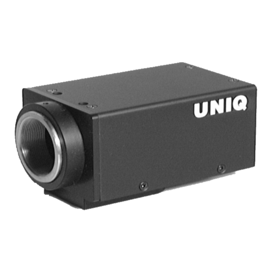
1. Introduction 1.1 General Description UM-300/UM-301 series is a near infrared (NIR) CCD camera. This camera is four times more sensitive than the conventional CCD camera at 945 nm wavelength. Smear is significantly reduced and dynamic range is much greater than the current CCD cameras. Asynchronous reset allows the image to be captured at very high shutter speed without smearing. -
Page 5: Camera Specifications
1.5 Camera Specifications Model UM-300 (EIA) UM-301 (CCIR) CCD Sensor ½” Interline-Transfer EXview HAD CCD Chip Size 6.4 mm x 4.8 mm Effective Pixels (H x V) 768 x 494 752 x 582 8.4 mm x 9.8 mm 8.6 mm x 8.3 mm... -
Page 6: Camera Setup
2.1 Basic Camera Setup For basic camera setup, as shown in Figure 1, one UM-300/UM-301 camera, one standard C-mount lens, one TV monitor, one PS-12C power supply unit or equivalent, and one BNC cable (75W) are required. Make sure the camera has the correct settings before powering up. -
Page 7: Camera Functions
3. Camera Functions 3.1 12-Pin Connector The 12-pin Hirose connector is located on the rear Pin No. Description Note plate of the camera. All ground signals on pin # 1, 3, +12V DC input 5, 8, 10, and 12 are common grounds. Although +12 V DC input is recommended on pin #2, this Video camera should withstand +12 V ±... -
Page 8: Gain Control Mode
3.4 Gain Control Mode (AGC/MGC) Automatic gain control (AGC): AGC/MGC switch is located on the rear plate. AGC factory setting is 2V for AGC control and 3V for AGC MAX control. Therefore, the maximum gain is about 18dB as shown in Figure 6 below. AGC setting cannot be changed through the rear gain potentiometer. Manual gain control (MGC): The manual gain control can be adjusted from 5dB to 18dB through the gain potentiometer on rear plate. -
Page 9: Field And Frame Mode (Fld/Frm)
3.6 Field and Frame Mode (FLD/FRM) Field Mode: Field/Frame mode switch is located on the rear panel. In field mode, two adjacent horizontal lines are combined and scanned out as shown in figure 8 shown below. There is one line offset between odd field and even field. The sensitivity in field mode is double for each field scanning (1/60 second). -
Page 10: Timing Signals
4. Timing Signals 4.1 Asynchronous Capture Mode (Shutter position from #1 to #8) Make sure NRM/ASM switch is set to ASM mode and FLD/FRM switch is set to FLD mode. The camera can be reset by providing an external vertical initialized pulse (VINT), see figure 9 shown below. The VINT pulse width is recommended to be greater than 1H, or 63.5 msec. -
Page 11: External Synchronization And Gen-Lock
Set NRM/ASM switch to ASM position and FLD/FRM switch to FRM mode. 4.5 External Synchronization and Gen-lock The UM-300/UM-301 camera automatically locks to the external sync source. The external sync source must match the camera HD and VD specification, which are 15.734KHz and 59.94Hz respectively. Both external HD and VD are TTL level signals. -
Page 12: Integration
4.6 Integration The UM-300/UM-301 camera can be integrated up to 2 seconds without severe noise or dark current effect. Make sure the camera is set to frame mode before preceding any integration; this will ensure that there will be a full frame video (both odd and even field). -
Page 13: Camera Malfunction
CCD glass surface or the CCD camera is partially damaged. Use high-pressure air to blow the dirt away if the CCD glass is not clean. If the problem still exists, contact the UNIQ technical support for help. If there is video on TV monitor but not with a frame grabber, most likely the problem is from the frame grabber's software or hardware.
Need help?
Do you have a question about the UM-300 and is the answer not in the manual?
Questions and answers