Table of Contents
Advertisement
One World, One Home
Commercial air condi
Use the installatio
Installation and Operation Manual of
Commercial Air Conditioner
This Manual applies to modular air-cooled (heat pump)
chiller units
Modle: CA0065EANR
This manual applies to
Air-cooled modular cold water (heat pump) unit
model:
CA0065EANR
This Manual applies to modular air-cooled (heat pump)
chiller units
Modle: CA0035EAND
CA0070EAND
CA0130EAND
Advertisement
Table of Contents

Related Manuals for Haier CA0065EANR


Summary of Contents for Haier CA0065EANR
- Page 1 Use the installatio Installation and Operation Manual of Commercial Air Conditioner This Manual applies to modular air-cooled (heat pump) chiller units Modle: CA0065EANR This manual applies to Air-cooled modular cold water (heat pump) unit model: CA0065EANR This Manual applies to modular air-cooled (heat pump)
- Page 2 We are always at your service. Haier – Sincere Forever! The Haier modular air-cooled unit you purchased may not be fully consistent with this Manual due to product improvement. We apologize for such inconvenience (if any) to you.
-
Page 3: Table Of Contents
Contents Safety Precautions ........................... 1 Product Introduction ........................... 4 Technical Data............................7 Performance Parameters ........................7 Unit Operating Range ......................... 8 Frequency Conversion Module Parameters ..................9 Installation ..............................10 Pre-installation Preparation ....................... 10 Drawing of Overall Dimension ......................11 Unit Base Diagram .......................... -
Page 4: Safety Precautions
Safety Precautions ■ Symbol description ◆ Dear user, For the better understanding of this Manual and the proper operation of the chiller, the marks and symbols used in this Manual are described as follows: WARNING: it is likely to cause death, serious injury and other severe accidents if the user fails to do as required. - Page 5 The installation location of the equipment should ensure that the drainage system is unblocked. Improper drainage systems may cause poor drainage and cause equipment to get wet. The unit must be warmed up for two hours for the first time. This is to protect the compressor. If the preheating time is not met, the unit may report the oil preheating and the temperature barrier.
- Page 6 CAUTION No unit is allowed to be installed near such places that are dirty, oily, salty, exposed to a large amount of sulfur gas and where the unit parts may be subjected to corrosion, such as toilet vent, operation room vent and sewage treatment equipment.
-
Page 7: Product Introduction
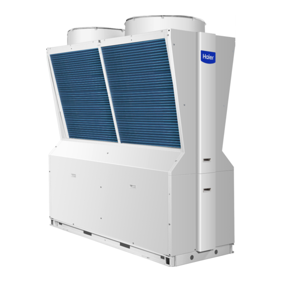
Product Introduction 1.1 Unit characteristics ■ Overview R410A-series modular air-cooled chiller unit is designed to satisfy users with the maximum reliability, safety and adaptability. The unit is well designed with aesthetic and elegant appearance. Additionally, with adaptable configuration, the unit can be connected to various specifications and types of fan coils or air handling units. - Page 8 1.2 Main components of the unit...
-
Page 9: Drawing Of Overall Dimension
1.3 Drawing of Overall Dimension ■ CA0065EANR (unit:mm) ■ Unit base diagram ■ Reference Position of Base 1. The foundation load is designed according to the weight of the unit during operation. 2. The foundation can be channel steel (designed by the user according to the unit size) or concrete structure. - Page 10 Technical Data 2.1 Performance Parameters Model CA0065EANR Item Nominal cooling capacity Nominal cooling power 19.2 Nominal cooling mode Partial load performance factor IPLV 4.49 Nominal cooling water flow m3/h 11.2 Nominal heat Nominal heating Nominal heating power mode Nominal hot water flow m3/h 12.2...
- Page 11 2.2 Unit operating range Cooling Heating 2.3 Unit operating conditions Item Contents Power supply voltage Within ±10% of the rated voltage Power supply frequency Within ±1% of rated frequency Phase imbalance Voltage difference between two phases of the power supply is less than 2% of the rated voltage Chilled water flow Within ±30% of the rated water flow...
- Page 12 2.4 Frequency conversion module parameters Ambient temperature/℃ Outlet temperature of air conditioner Cooling Cooling Cooling Cooling Cooling Cooling Cooling /℃ Capcity Capcity Capcity Capcity Capcity Capcity Capcity 1.27 1.18 1.11 1.02 0.96 0.83 0.78 1.30 1.22 1.15 1.07 1.00 0.87 0.81 1.33 1.26...
- Page 13 Installation Pre-installation Preparation ◆ Cargo inspection All units are firmly bolted on wood trays, subject to ex-factory inspection and filled with accurate amount of R410a refrigerant and refrigeration oil for the unit operation. Upon the receipt, you shall carefully inspect cargoes for any damage during transport and confirm all ordered parts and accessories are delivered.
- Page 14 Installation 1.Diagram of installation space for single chiller unit (Unit:mm) Guiding device 2.Diagram of installation space for multiple chiller units (Unit:mm) >450 >1500 >1500...
- Page 15 Installation 3.Diagram of arrangement of multiple chiller units (Unit: mm)
-
Page 16: Water Pipe Connection
Installation Water Pipe Connection External water pipe system must be equipped with flexible joints, water filter, electronic cleaner, check valve, drain valve, exhaust valve, shutoff valve, expansion tank, etc.. The expansion tank shall be located at 1-1.5 m above the highest point of the system; the exhaust valve shall be set between the highest point of the system and the expansion tank, and insulations shall be arranged between the tank and the pipe. - Page 17 WARNING Never connect unclean pipe to the unit! If the unit is to idle for a long time, the water in the water system shall be drained to prevent the plate heat exchanger being iced. If the unit is to idle for a short time, the power-off is not allowed, because the unit has automatic anti-freezing function.
-
Page 18: Schematic Diagram Of Water System
Installation Schematic diagram of water system Symbol Symbol Description Description Fan co il Check valve Wate r pump A utomatic exhaust valve Flexible co nnection Water filter E xpansion tank Fan co il S top va lve Electronic water processor Fan co il Thermometer 3 -way valve... -
Page 19: Air Conditioning Piping System Design
Basic requirements The chilled water pipelines may be connected as per relevant procedure when the unit is installed in place. Such pipelines shall be free from any foreign matter, and must conform to local piping regulations and rules. Before unit operation, thoroughly flush all chilled water pipelines to ensure that they are free from any foreign matter. - Page 20 conditioning part load operation; Energy-saving technical measures should be adopted as much as possible in the design of air-conditioning piping systems; The pipe and fittings used in the piping system should meet the local requirements; Pay attention to the maintenance and management of the piping system design, easy to operate and adjust.
-
Page 21: Expansion Tank Volume Calculation
◆ Water system volume calculation example Assume that two CA0065EANR module units are installed in a water system, and the return water temperature is set to 12 degrees. The main pipe diameter is DN65. The total length of the inlet and outlet pipes is 80m. -
Page 22: Electrical Connection
Users must not remove and add control components privately. Haier Company shall not be liable for any damage to the unit and personal injury caused by failure to operate in accordance with these Rules. -
Page 23: Electrical Parameters
Maximum current Starting current Reference cable cross section CA0065EANR 5X10mm Note: The working voltage of the unit must be within ± 10% of the rated working voltage. If the wiring distance of the power supply line is too long, the power cable diameter should be increased. It is recommended to refer to the technical information of the cable manufacturer under the guidance of a professional electrician. - Page 24 (factory default) (factory default) model boot selection CA0065EANR Address setting: all OFF for the host DIP1 is the low bit, DIP4 is the high bit, and so on, the address: DIP1, DIP2, DIP3, DIP4 settings see attached table. Unit number address...
- Page 25 4.4.Communication line connection diagram 4.5.The connection diagram of the handheld device The Communicator reserves the docking terminal and is equipped with a 5 meter communication cable. The handheld communicator 12V (red), GND (black), A (green), B (white) and the 12V on the terminal block of the electrical control box respectively.
- Page 26 Compressor drive module Capacitor plate Lightning protection board Refrigerant heat sink Reactance...
- Page 27 The highest and lowest values of the reference standard are judged as the reference standard for the maximum working condition and the minimum working condition of the unit. If the unit is stable and exceeds the reference standard, please consult your local dealer and Haier for sale.
-
Page 28: Maintenance
Repair and maintenance 6.1 Regular inspection of the project Before delivery, the unit has been rigorously tested and inspected to ensure that the product has good performance after leaving the factory. In order to ensure long-term good operation of the unit, the user should carry out regular maintenance and maintenance. - Page 29 maintenance plan can be carried out according to different usage conditions in different regions. Description: ● for user self-test items; ★ check items for professionals...
-
Page 30: Faults And Treatment Methods
Faults and treatment methods 7.1 Fault Code Query (01 represents the A system,02 represents the B system) Fault code Fault description Remarks Fault in air-condition flow switch One lock Compressor module three-phase AC input phase 4 times in 60min, E05(-01/02/) sequence mission protection locked. - Page 31 rotating locked. E47(-01/02) Compressor reverse phase detection protection One lock E48(-01/02) Fault in overcurrent protection of system fan One lock 3 times in 60min, E49(-01/02) High-pressure protection of system locked. 3 times in 60min, E51(-01/02) Over-current protection of system compressor locked.
- Page 32 7.2 Common faults and handling Fault description Possible cause Troubleshooting Remarks 1.Air or non-condensable gas found in the system Discharge and empty, if necessary, the Cooling/heating non-condensable gas Refer to “High Suction Pressure" 2.High suction pressure Cooling/heating 3.Undesirable high-pressure switch Replace the high-pressure switch Cooling/heating 4.Dirty or clogged fin of the condenser...
- Page 33 Fault description Possible cause Troubleshooting Remarks 1.Air found in the water system Discharge air via the exhaust valve 2.Water-side heat exchanger scaling or with foreign Clean up the incrustation scale matters inside 3.Poor switch Replace the target flow switch Fault in flow Cooling/heatin switch Adjust the flow in water pipelines via the...
-
Page 34: Water Quality Management
Water quality management 8.1 Water quality requirements The water in the water system should be softened first to prevent scaling in the heat exchanger and affect the heat transfer effect. In addition, unsoftened water may also foul in the pipeline, causing increased water resistance, affecting water flow and pump work. - Page 35 Closed recirculation system, open recirculation system, DC water system comparison: DC water system Open recirculation system Closed recycling system Fouling 1.1 a surfactant, such as 1.1.Emissions No need to control control polyphosphate 1.2.surfactants, such as polyphosphate 1.2. Increase in acidity 1.3.
-
Page 36: Warranty Declaration
Warranty Declaration Dear users, Thank you for selecting and using Haier products. Based upon relevant regulations stipulated in the Law of the People's Republic of China on Protection of Consumer Rights and Interests as well as our sincere commitments to you, we offer you the following services by virtue of the warranty and invoice:...
Need help?
Do you have a question about the CA0065EANR and is the answer not in the manual?
Questions and answers