
Related Manuals for Metrolab FDI 2056


Summary of Contents for Metrolab FDI 2056
- Page 1 Magnetic precision has a name Fast Digital Integrator FDI 2056 User's Manual Version 2.0 (Revision 1.1) March 2013...
- Page 2 FDI2056 User’s Manual v 2.0 r 1.1 – 03/13 Copyright © 2013 Metrolab Technology SA REVISION HISTORY v. 1.0 r. 1.0 June 2010 First release v. 1.0 r. 1.1 June 2010 Update installation procedure Improve readability of screen-shots Correct section numbering in Chapter 4 Correct formatting of specifications table v.
-
Page 3: Table Of Contents
1- Introduction ....................... 1 GETTING STARTED ....................3 2- Installation Guide ....................3 2-1 FDI 2056 Host Interface panel and connections ..................3 2-2 FDI 2056 front panel and connections ....................4 2-2-1 Description of the encoder input Micro-D connector..............5 2-3 Communicating with the FDI 2056 ...................... - Page 4 FDI2056 User’s Manual v 2.0 r 1.1 – 03/13 Copyright © 2013 Metrolab Technology SA 3-7-27 :SENSe#:SAMPler[:RATe] ......................30 3-7-28 :SENSe#:FUNCTion ........................30 3-7-29 :SYSTem:HELP:HEADers? (Query only) ................... 31 3-7-30 :SYSTem:HELP:SYNTax? (Query only) ................... 31 3-7-31 :SYSTem:CHAnnel#:CDATe? (Query only) ................31 3-7-32 :SYSTem:CHAnnel#:MDATe? (Query only) ................
- Page 5 FDI2056 User’s Manual v 2.0 r 1.1 – 03/13 Copyright © 2013 Metrolab Technology SA 5-4 Adding a supplementary integrator channel ..................79 5-5 Warranty, Calibration, Certification and Maintenance ................82 www.metrolab.com...
-
Page 6: Getting Started
It is easy to develop custom software for the FDI 2056, especially in LabVIEW, using Metrolab’s FDI 2056 Application Programming Interface (API). Finally, keep your FDI 2056 accurate and up to date by having it recalibrated at regular intervals. The recommended calibration interval is every 12 months. At this time, Metrolab will also install the latest available firmware. - Page 7 If you have problems and your retailer cannot help you further, the Metrolab team is ready to help. Even if you don’t have problems, we are always interested in knowing more about how our instruments are used. Feel free to contact us at any time at contacts@metrolab.com.
-
Page 8: Getting Started
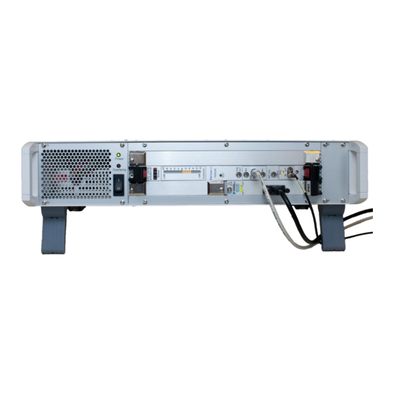
This chapter provides information regarding the various connections available on the instrument and other internal configurations available to the user. 2-1 FDI 2056 HOST INTERFACE PANEL AND CONNECTIONS The DVI (Digital Visual Interface) is used to connect the host interface to a display device, such as a computer monitor. -
Page 9: Fdi 2056 Front Panel And Connections
See section 2-2-1 for the connector pinning description. The coil can be connected to the FDI 2056 either via the two LEMO 00 connectors, “IN+” and “IN-“, or via the single LEMO 0B connector. -
Page 10: Description Of The Encoder Input Micro-D Connector
2-2-1 Description of the encoder input Micro-D connector. The FDI 2056 is supplied with a 50-cm cable with a Micro-D connector. The color in the table below refers to this cable. Pin n°... -
Page 11: Communicating With The Fdi 2056
2-4 INITIAL POWER-ON 1. After the FDI 2056 is powered on, the message “INIT” will be displayed on all installed channels. This indicates that the FDI 2056 is resetting. Once powered on, the FDI 2056 takes several seconds before being able to communicate. -
Page 12: Software Development
Insert the installation CD. Copy the Source folder to your hard drive. The API subfolder contains the Application Programming Interface. Modify the FDI 2056 measurement software, or write a measurement system from scratch using the LabVIEW development system. www.metrolab.com... -
Page 13: Programming The Fdi 2056
PROGRAMMING THE FDI 2056 3- VXI & SCPI standard interfaces 3-1 HOST INTERFACE The FDI 2056 and its associated host software support an Ethernet interface. The native host interface protocol is based on the following standards, very widespread in the instrumentation industry: - VXI-11: Ethernet device control, - SCPI: command structure. - Page 14 2.0 r 1.1 – 03/13 Copyright © 2013 Metrolab Technology SA :FORMat … FORMat Set output format HCOPy Not used in the FDI 2056 :INPut … INPut Configure gain and coupling INSTrument Not used in the FDI 2056 MEMory...
-
Page 15: Ieee 488.2 / Scpi Status Registers
SCPI standard, provides a good summary. This section describes how the FDI 2056 uses these status registers. 3-3-1 Status Byte Contains a 1-byte status summary. The FDI 2056 uses the following bits: Name Description Error AVailable (in Error/Event Queue) -
Page 16: Standard Event Status Register
Copyright © 2013 Metrolab Technology SA Name Description Operation Summary Bit 3-3-2 Standard Event Status Register Memorizes certain standardized events. The FDI 2056 uses the following bits: Name Description Operation Complete *OPC has flagged operation complete Query Error Error in preceding query... -
Page 17: Operation:pararameters
FDI2056 User’s Manual v 2.0 r 1.1 – 03/13 Copyright © 2013 Metrolab Technology SA Name Description Waiting for ARM Waiting for arm CORRecting Correcting the offset or the slope Parameters Parameter has changed Data available Internal data buffers are not empty... - Page 18 Event Register (EVENt) Transitions in a Condition Register are memorized in the corresponding Event Register. Most FDI 2056 registers only latch transitions from 0 to 1, some are configurable using the Positive and Negative Transition Register set. Event Registers are cleared when read.
-
Page 19: Ieee 488.2 Controls
IEEE 488.1 (HPIB or GPIB). Not all functions are supported in VXI-11. In addition, some of these functions are not supported on the FDI 2056; the Description column will note whether the function has no effect or whether it returns an error. -
Page 20: Scpi Command Syntax
FDI2056 User’s Manual v 2.0 r 1.1 – 03/13 Copyright © 2013 Metrolab Technology SA Command Name Description *IDN? Identification query Returns following information: manufacturer; model; serial number; and version of electronics and firmware. Note that this query returns “Arbitrary ASCII Response Data”... -
Page 21: Scpi Command Description
N = nano (10 U = micro (10 M = milli (10 K = kilo (10 MA = mega (10 G = giga (10 The FDI 2056 recognizes the following units: Base unit Multiplier Description M, U, N Weber M, U, N... -
Page 22: Abort (Event)
FDI2056 User’s Manual v 2.0 r 1.1 – 03/13 Copyright © 2013 Metrolab Technology SA A question mark (?) appended to the command and “Query only” indicates query-only commands. A command generating an internal event is identified as “Event”. All commands are listed in alphabetic order, excluding IEEE 488.2 commands starting with an asterisk (*) which are described in section 3-5 and excluding STATus command which are described in section 3-3. -
Page 23: Arm#[:Sequence][:Layer]:Encoder
FDI2056 User’s Manual v 2.0 r 1.1 – 03/13 Copyright © 2013 Metrolab Technology SA INTernal Specifies that the arm source is fed internally. Used only on an instrument having multiple channels which need to work synchronously. TIMer Specifies that the arm source is fed by the internal periodic signal source. -
Page 24: Arm#[:Sequence][:Layer]:External[:Slope]
FDI2056 User’s Manual v 2.0 r 1.1 – 03/13 Copyright © 2013 Metrolab Technology SA ARM#:SYNChro? [DEFault|OPTions] NONe Default Arguments POSitive A transition from low to high of the synchronization signal found on the encoder connector is used to leave the arm level. -
Page 25: Calculate#:Timestamp[:Cumulative]
FDI2056 User’s Manual v 2.0 r 1.1 – 03/13 Copyright © 2013 Metrolab Technology SA Syntax CALC#:FLUX[:CUMUlative] Boolean|DEFault CALC#:FLUX[:CUMUlative]? [DEFault] Default Arguments Disables the accumulation. Enables the accumulation. Example If a constant voltage of 1 volt is fed to the system configured to measure a partial integral every 1 second, every partial integral will evaluate to 1 [WB]. -
Page 26: Control#:Encoder:configure
FDI2056 User’s Manual v 2.0 r 1.1 – 03/13 Copyright © 2013 Metrolab Technology SA will result in the system reporting for the first three timestamp values : 1.00e-3 S;…, 2.00e-3 S;…, 3.00e-3 S;…, …. If the accumulation mode is unset, the system will report for the first three values : 1.00e-3 S;…, 1.00e-3 S;…, 1.00e-3 S;…, …. -
Page 27: Control#:Encoder[:Position]
The value of this counter is available by using the command CONTR#:ENC:POS? When configuring the FDI 2056 to use an encoder, it is of upmost importance to check that the rotational direction is in accordance with the two LEDs denoted FW and BW located on the front panel of the channel into which the encoder is plugged. -
Page 28: Diagnostic:upgrade:[Initiate] (Event)
Syntax DIAGnostic:UPGRade[:INITiate] NOTICE The :DIAGnostic:UPGRade:[INITiate] command is intended for use by the manufacturer only. It can cause your FDI 2056 to become nonoperational. 3-7-12 :DISPlay#:TEXT[:DATA] Displays some text on the 4-digit display located on the channel front panel. Syntax DISPlay#:TEXT[:DATA] <string>... -
Page 29: Format#:Data
FDI2056 User’s Manual v 2.0 r 1.1 – 03/13 Copyright © 2013 Metrolab Technology SA FORMat#:DATa FORMat#:TIMestamp[:ENABle] FORMat#:READings:ALL FORMat#:UNIT[:ENABle] UNIT#:FLUX UNIT#:VOLTage UNIT#:TIMestamp 3-7-14 :FORMat#[:DATa] Sets format for returned measured data. Syntax FORMat#[:DATa] ASCii|INTeger|DEFault FORMat#[:DATa]? [DEFault|OPTions] ASCii Default Arguments ASCii User-readable output. -
Page 30: Format:timestamp[:Enable]
FDI2056 User’s Manual v 2.0 r 1.1 – 03/13 Copyright © 2013 Metrolab Technology SA SENSe#:FUNCtion 3-7-15 :FORMat:TIMestamp[:ENABle] Determines if the timestamp must be sent when reading measurement results. Syntax FORMat:TIMestamp[:ENABle] <Boolean>|DEFault FORMat:TIMestamp[:ENABle]? [DEFault] Default Arguments Disables the timestamp readout. -
Page 31: Format:unit[:Enable]
FDI2056 User’s Manual v 2.0 r 1.1 – 03/13 Copyright © 2013 Metrolab Technology SA 3-7-17 :FORMat:UNIT[:ENABle] Determines if the measurement results must be followed by the unit. FORMat#:UNIT[:ENABle] <Boolean>|DEFault Syntax FORMat#:UNIT[:ENABle]? [DEFault] Default Arguments Disables the unit readout. Enables the unit readout. -
Page 32: Measure#[:Scalar]:Voltage? (Query Only)
FDI2056 User’s Manual v 2.0 r 1.1 – 03/13 Copyright © 2013 Metrolab Technology SA Syntax INPut#:GAIN MINimum|MAXimum|UP |DOWN|DEFault|<value> INPut#:GAIN? [DEFault|OPTions] Default Arguments MINimum Sets the input gain to its minimal value. MAXimum Sets the input gain to its maximal value. -
Page 33: Memory :Store[:State] (Event)
FDI2056 User’s Manual v 2.0 r 1.1 – 03/13 Copyright © 2013 Metrolab Technology SA 3-7-21 :MEMory :STORe[:STATe] (Event) Store the current user’s settings in local hard-drive. MEMory:STORe[:STATe] Syntax Example MEM:STOR Store the current system state into the local hard-drive... -
Page 34: Sense#:Correction:all[:Acquire] (Event)
FDI2056 User’s Manual v 2.0 r 1.1 – 03/13 Copyright © 2013 Metrolab Technology SA FORMat#:DATa FORMat#:TIMestamp[:ENABle] FORMat#:READings:ALL FORMat#:UNIT[:ENABle] UNIT#:FLUX UNIT#:VOLTage UNIT#:TIMestamp 3-7-24 :SENSe#:CORRection:ALL[:ACQuire] (Event) Proceeds to an offset and slope correction over all available gain on a channel. When proceeding to the offset correction, the input is not short-circuited. It’s up to the user to proceed to that operation if needed. -
Page 35: Sense#:Correction:slope[:Acquire] (Event)
FDI2056 User’s Manual v 2.0 r 1.1 – 03/13 Copyright © 2013 Metrolab Technology SA 3-7-26 :SENSe#:CORRection:SLOPe[:ACQuire] (Event) Proceed to an offset and slope correction on a channel. When proceeding to the offset correction, the input is not shorted. It’s up to the user to proceed to that operation if needed. -
Page 36: System:help:headers? (Query Only)
FDI2056 User’s Manual v 2.0 r 1.1 – 03/13 Copyright © 2013 Metrolab Technology SA This command turns the sense subsystem off. No value can be read from that channel in that mode. 3-7-29 :SYSTem:HELP:HEADers? (Query only) Returns all commands known by the system. -
Page 37: System:channel#:Hwversion? (Query Only)
FDI2056 User’s Manual v 2.0 r 1.1 – 03/13 Copyright © 2013 Metrolab Technology SA Thu Jan 01 13:53:19 2009\n 3-7-33 :SYSTem:CHAnnel#:HWVERsion? (Query only) Returns the hardware version of the specified channel. Syntax SYSTem:CHAnnel#:HWVERsion? SYST:CHA1:HWVERsion? Example This command might return CORE v1.3-PXI|DISPLAY v1.0|MEMORY v1.0\n... -
Page 38: System:serial? (Query Only)
FDI2056 User’s Manual v 2.0 r 1.1 – 03/13 Copyright © 2013 Metrolab Technology SA PDI5025 The language switch is made immediately, leading to an instant loss of communication, as the PDI5025 idiom is carried through a serial communication port. -
Page 39: Trigger#[:Sequence]:Source
FDI2056 User’s Manual v 2.0 r 1.1 – 03/13 Copyright © 2013 Metrolab Technology SA Syntax SYSTem:CHAnnel[:COUNt]? Example SYST:CHA? Returns the number of channels available in the system. 3-7-41 :TRIGger#[:SEQuence]:SOURce Selects the source for the trigger event detector. Only one source may be specified at a time. -
Page 40: Trigger#[:Sequence]:Count
FDI2056 User’s Manual v 2.0 r 1.1 – 03/13 Copyright © 2013 Metrolab Technology SA Example TRIG:SOUR TIM Sets the trigger event to TIMer. 3-7-42 :TRIGger#[:SEQuence]:COUNt Determines the number of triggers needed to perform a full measurement. TRIGger#[:SEQuence]:COUNt <numerical value (no unit)>... -
Page 41: Trigger#[:Sequence]:Encoder[:Direction]
FDI2056 User’s Manual v 2.0 r 1.1 – 03/13 Copyright © 2013 Metrolab Technology SA Default POSitive Arguments POSitive A transition from low to high of the trigger-in signal located on the front-panel is used to exit the trigger level. -
Page 42: Programming Hints
"System / Peripherals & Interfaces / VISA TCP/IP Resources" or “… / USB Resources”, select the FDI 2056 and click the "Open VISA Test Panel" icon. This opens a window from which you can try all functions available through NI-VISA. - Page 43 “Command Reference”, provide a generic description of all possible error codes. In general, the codes are between -800 and 300. This chapter describes only the error codes produced by the FDI 2056, and the circumstances that might produce each error. NO ERROR Zero indicates no error.
- Page 44 Indicates that a query was received in the same program after indefinite response message after a query requesting an indefinite response was executed. On the FDI 2056, the only command returning an indefinite response (“Arbitrary ASCII Response Data”) is *IDN.
-
Page 45: Using The Pdi Emulation Mode
The PDI emulation mode offers a way to help customers who have already extensively used the PDI 5025 in the past, to integrate easily this new instrument in their existing installation. However, the FDI 2056 is based on a completely different system and therefore some functionality present in the PDI 5025 have been transformed or removed. -
Page 46: Configuration
During the following explanations, the red flag () symbol, signifies a change between the PDI 5025 original behavior and the new emulation one. 4-2 CONFIGURATION Before using the FDI 2056 in its PDI 5025 emulation mode, some parameters must be set according to the user’s specific hardware interface and bi-phase encoder. - Page 47 FDI2056 User’s Manual v 2.0 r 1.1 – 03/13 Copyright © 2013 Metrolab Technology SA RGA command is issued, the returned gain value is the one given during the SGA command, not the substituted value. Gain_2 Numeric 0.1, 0.2, 0.4, 0.5, 1, 2, 4, 5, 10, 20, 40, 50, 100 ...
- Page 48 FDI2056 User’s Manual v 2.0 r 1.1 – 03/13 Copyright © 2013 Metrolab Technology SA 14400, 19200, 28800, 38400, 57000, 57600, 115200, 128000, 230400 ByteSize Numeric 7, 8 FlowControl Flow control none enumeration xonxoff ctsrts Parity Parity...
-
Page 49: Motor Software Interface
SYNC input takes precedence over the ERROR function. 4-3 MOTOR SOFTWARE INTERFACE Since the FDI 2056 does not incorporate a motor driver, and since the PDI 5025 ( which di provide such interface) offered a set of command to handle the motor,... -
Page 50: Power On Sequence
Thus, any messages sent to the FDI 2056 will be ignored. 4-5 CHANNEL SELECTION The FDI 2056 can be equipped with as many as nine channels (the standard unit is equipped with a single channel). All channels are always triggered in parallel. -
Page 51: Offset Adjustment
FDI2056 User’s Manual v 2.0 r 1.1 – 03/13 Copyright © 2013 Metrolab Technology SA Example: SGA,B,100 set gain to 100 on channel B SGA,20 set gain to 20 on the active channel(s). We recommend that the gain be set in such a manner that the voltage displayed on the bargraph display is the highest possible without an over-range being detected during the measurement cycle. -
Page 52: Trigger Source: Timer
The internally quartz controlled time base generator is set by default to operate at a frequency of 1 [kHz] and is used to feed the FDI 2056 Trigger Factory. The TRI command defines the integration intervals in terms of number of periods – As the default frequency is 1 [kHz], you may consider this integration interval as the time spent for each partial integral expressed in milliseconds. -
Page 53: Trigger Source: Bi-Phase Encoder
FDI2056 User’s Manual v 2.0 r 1.1 – 03/13 Copyright © 2013 Metrolab Technology SA by the RUN command. In this case the TRS command - which will have to have been issued before - must be TRS,T. by the first external synchronization signal on the SYNC input which follows the RUN command issued by the host. -
Page 54: Trigger Source: External
FDI2056 User’s Manual v 2.0 r 1.1 – 03/13 Copyright © 2013 Metrolab Technology SA IND,- Turn the motor in the backwards direction (BW) until the index pulse is detected. TRI,-,140/8,10/3,1000 Prepares sequence measurements in the backward direction, the first TRIGGER is at absolute position 140 (pulses, not cycles). - Page 55 FDI2056 User’s Manual v 2.0 r 1.1 – 03/13 Copyright © 2013 Metrolab Technology SA The external trigger source (the active edge of which can be selected by software – Please refer to chapter 4-2) must be connected to the input denoted “External Trigger: IN”...
-
Page 56: The Pdi 5025 Status Registers
FDI2056 User’s Manual v 2.0 r 1.1 – 03/13 Copyright © 2013 Metrolab Technology SA 4-10 THE PDI 5025 STATUS REGISTERS The PDI 5025 has seven internal status registers that can be accessed by the user. These registers can be used to interrogate the instrument about its current state. - Page 57 FDI2056 User’s Manual v 2.0 r 1.1 – 03/13 Copyright © 2013 Metrolab Technology SA (when waiting for a synchronization. signal or the absolute value of the first trigger, for example). After this first trigger, an over-range condition aborts the measurement cycle immediately and has a similar effect to the reception of a BRK command (see section 4-11-7).
- Page 58 FDI2056 User’s Manual v 2.0 r 1.1 – 03/13 Copyright © 2013 Metrolab Technology SA Bit 6 This bit is always read as 0. Bit 5 This bit is always read as 0. Bit 4 Power on reset This bit is set at power on.
- Page 59 An infinite sequence is set using ni=* in the TRI command. Bit 3 Measurement in progress This bit is set to indicate that the FDI 2056 is in the process of measuring. The bit is automatically set by the RUN command; it is automatically cleared when the sequence is terminated.
- Page 60 FDI2056 User’s Manual v 2.0 r 1.1 – 03/13 Copyright © 2013 Metrolab Technology SA Table 4-3 S 3: Trigger source TATUS STATUS 4 Integrator Channel (1 Byte) Access to integrator channel status for channel C to I are accessed using the CHA command.
- Page 61 FDI2056 User’s Manual v 2.0 r 1.1 – 03/13 Copyright © 2013 Metrolab Technology SA When the negative over-range LED on the bargraph display of the channel is lit, this bit is set. Bit 0 Positive over-range This bit reports the instantaneous positive over-range status.
- Page 62 This bit is similar to bit 4 of STATUS Bit 3 Run active This bit is set to indicate that the FDI 2056 is taking measurements. This status bit is similar to bit 3 of STATUS Bit 2 Data Transfer Mode When set, this bit indicates that the immediate data transfer mode (IMD,1) is selected.
-
Page 63: Data Acquisition
If the command NBO,1 has been sent previously to the FDI 2056, the cumulative value is cleared to 0 (zero) at each occurrence of an over-range. At the end of a run, the number of available measurements data is identical to the number of integration periods. -
Page 64: Direct Data Transfer (Imd,1)
FDI2056 User’s Manual v 2.0 r 1.1 – 03/13 Copyright © 2013 Metrolab Technology SA 4-11-4 Direct Data Transfer (IMD,1) This is the default data transfer mode. Measured data are read individually. As soon as the measured data have been processed, the “Data-Ready” bit in STATUS 1 is set. -
Page 65: End Of Data (Eod)
The external trigger input is disabled. All data measured up to the instant that the BRK was received are valid and can be read by the host. The FDI 2056 can also execute a BRK automatically if any of the following errors occurs: www.metrolab.com... -
Page 66: Automatic Use Of A Motor (Mot,A)
4-11-9 Autotest (TST and AUT) Each time the FDI 2056 is powered up it performs an autotest, which lasts five seconds and performs five preset measurements and verifies the results. During the autotest the display shows the word "Test". Once finished, if the autotest was successful, the display will show the channel to which it is assigned and the current value of the gain. -
Page 67: Offset Compensation (Isc, Adj)
FDI2056 User’s Manual v 2.0 r 1.1 – 03/13 Copyright © 2013 Metrolab Technology SA The analog input circuitry doesn’t perform as it should. !INP This is a major issue, please contact us. !RNG The over-range detection mechanism does not perform as expected. -
Page 68: Pdi 5025 Emulated Commands
CHA,B Select channel B. CHA,* Select both channels A and B. Note: This command is valid only if the FDI 2056 is equipped with two channels. Trigger source selection (see section 6.6). TRS,T Default Timer (without external synchronization). TRigger Source,... - Page 69 FDI2056 User’s Manual v 2.0 r 1.1 – 03/13 Copyright © 2013 Metrolab Technology SA SYNTAX DESCRIPTION MNEMONIC TRS,E,d..d Rotational incremental encoder with d..d TRigger Source, cycles per turn and with index signal. rotational Encoder Note: The decoder module counts 4 pulses for each encoder cycle.
- Page 70 FDI2056 User’s Manual v 2.0 r 1.1 – 03/13 Copyright © 2013 Metrolab Technology SA SYNTAX DESCRIPTION MNEMONIC TRI,s,a/n1,C1/n2,C2/.../n20,C20 TRIgger sequence The direction of displacement : + or - The absolute position of the start (1st trigger): -2 31 to 2 31 -1.
- Page 71 0 of 1 is set. STATUS Motor interface: Please read section 4-3 We remind you that the FDI 2056 doesn’t incorporate a motor driver. MOT,s Starts the motor. MOTor s = + starts the motor in the forward...
- Page 72 The cumulative value from the start of the measurement is stored in memory at the end of each integration interval. If the command NBO,1 has previously been sent to the FDI 2056, the cumulative value is cleared to 0 at each occurrence of an over- range. CUM,1,L Only the last cumulative value is stored and available for reading.
- Page 73 FDI2056 User’s Manual v 2.0 r 1.1 – 03/13 Copyright © 2013 Metrolab Technology SA SYNTAX DESCRIPTION MNEMONIC incompatible with the block data transfer (IMD,0) and forces an immediate data transfer mode (IMD,1). See section 4-11 which explains timing limitations.
- Page 74 FDI2056 User’s Manual v 2.0 r 1.1 – 03/13 Copyright © 2013 Metrolab Technology SA SYNTAX DESCRIPTION MNEMONIC Note: this command can only be used when TRS,X or TRS,X,S has been previously executed. A typical application of this command is to disable unwanted external trigger pulses.
- Page 75 If many channels are active, A is the active channel by default. Reads the counter of the Trigger Factory. Read CounTer After reading the counters, the FDI 2056 converts the result to decimals and transfers it in the format +/- ddd..d. Leading zeroes are suppressed.
- Page 76 FDI2056 User’s Manual v 2.0 r 1.1 – 03/13 Copyright © 2013 Metrolab Technology SA SYNTAX DESCRIPTION MNEMONIC automatic test performed following the power on sequence or following the TST command. ISC,i,0 Default Internal short-circuit of channel "i": OFF Input Short Circ.
-
Page 77: Reference
FDI2056 User’s Manual v 2.0 r 1.1 – 03/13 Copyright © 2013 Metrolab Technology SA REFERENCE 5- Technical Details 5-1 DIGITIZER PERFORMANCE Parameter Conditions Unit ADC RESOLUTION ANALOG INPUT Differential voltage range (full-scale FS) ±5 V on each input leg ±10... - Page 78 FDI2056 User’s Manual v 2.0 r 1.1 – 03/13 Copyright © 2013 Metrolab Technology SA Memory mapping (unless mentioned, all registers are readable / writable) Offset BAR2 0x000 Read : Data, Write : Trigger configuration FIFO. BAR3 0x100 Status Mode...
- Page 79 FDI2056 User’s Manual v 2.0 r 1.1 – 03/13 Copyright © 2013 Metrolab Technology SA 0101 : Bi-Phase Pulses positive direction 0110 : Bi-Phase Pulses negative direction 0111 : Bi-Phase Pulses 1000 : Bi-Phase Target Bits 27..16 Trigger prescaler. Bits 15..0 Triggers count A value of 0 will be interpreted as infinite count.
- Page 80 FDI2056 User’s Manual v 2.0 r 1.1 – 03/13 Copyright © 2013 Metrolab Technology SA Acquisition and Trigger must be started before any triggers can be sent. It means also that the Self Trigger cannot be started simultaneously with the two others. Otherwise, the first partial integral might be wrong.
- Page 81 FDI2056 User’s Manual v 2.0 r 1.1 – 03/13 Copyright © 2013 Metrolab Technology SA 20.0 40.0 50.0 100.0 13 to 15 Any other value could result in a gain change and should be avoided. Signal path and voltage reference configuration (BAR3 : 0x105)
- Page 82 FDI2056 User’s Manual v 2.0 r 1.1 – 03/13 Copyright © 2013 Metrolab Technology SA External Trigger configuration (BAR3 : 0x106) Bit 1..0 Active edge configuration 00 : Disabled 01 : Rising edge 10 : Falling edge 11 : Both edges Bi-Phase decoder configuration (BAR3 : 0x107) Bit 7..6...
- Page 83 FDI2056 User’s Manual v 2.0 r 1.1 – 03/13 Copyright © 2013 Metrolab Technology SA configuration” Bit 5 Error detected on Bi-Phase decoder: edge count incorrect at index. Writing a value again in the “Bi-Phase decoder: maximum count” register will reset this bit.
-
Page 84: Input Adaptation
5-4 ADDING A SUPPLEMENTARY INTEGRATOR CHANNEL The FDI 2056 usually comes with one channel but can be equipped with up to three integrator channels on the standard Metrolab crate and up to nine integrator www.metrolab.com... - Page 85 FDI2056 User’s Manual v 2.0 r 1.1 – 03/13 Copyright © 2013 Metrolab Technology SA channels with the extended crate. To install an FDI 2056 integration card in the crate, please follow the instructions bellow carefully. CAUTION The FDI 2056 electronics supports hot-swapping, but the firmware will not start up correctly.
- Page 86 FDI2056 User’s Manual v 2.0 r 1.1 – 03/13 Copyright © 2013 Metrolab Technology SA PXI cards use a locking card extractor. When inserting the card: Push the levers outward; Push the card in until the black plastic extractor levers touch the crate;...
- Page 87 FDI2056 User’s Manual v 2.0 r 1.1 – 03/13 Copyright © 2013 Metrolab Technology SA 5-5 WARRANTY, CALIBRATION, CERTIFICATION AND MAINTENANCE Warranty 2 years Recommended calibration interval: 12 months Maintenance None NOTICE This product conforms to the WEEE Directive of the European Union (2002/96/EC) and belongs to Category 9 (Monitoring and Control Instruments).
Need help?
Do you have a question about the FDI 2056 and is the answer not in the manual?
Questions and answers