Advertisement
SPLIT-TYPE, HEAT PUMP AIR CONDITIONERS
2018
TECHNICAL & SERVICE MANUAL
Series SEZ
Model name
Model name
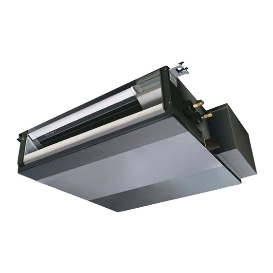
<Indoor unit>
<Indoor unit>
SEZ-M25DA(L)
SEZ-M35DA(L)
SEZ-M50DA(L)
SEZ-M60DA(L)
SEZ-M71DA(L)
INDOOR UNIT
ON/OFF
TEMP
WIRED REMOTE
WIRELESS REMOTE
CONTROLLER
CONTROLLER
(optional)
(supplied)
for DA type
for DAL type
Advertisement

Related Manuals for Mitsubishi Electric Mr.SLIM SEZ Series


Summary of Contents for Mitsubishi Electric Mr.SLIM SEZ Series
- Page 1 SPLIT-TYPE, HEAT PUMP AIR CONDITIONERS 2018 TECHNICAL & SERVICE MANUAL Series SEZ Model name Model name <Indoor unit> <Indoor unit> SEZ-M25DA(L) SEZ-M35DA(L) SEZ-M50DA(L) SEZ-M60DA(L) SEZ-M71DA(L) INDOOR UNIT ON/OFF TEMP WIRED REMOTE WIRELESS REMOTE CONTROLLER CONTROLLER (optional) (supplied) for DA type for DAL type...
-
Page 2: Table Of Contents
CONTENTS 1. SAFETY PRECAUTION ......... . 2 2. -
Page 3: Safety Precaution
SAFETY PRECAUTION MEANINGS OF SYMBOLS DISPLAYED ON THE UNIT This mark is for R32 refrigerant only. Refrigerant type is written on nameplate of outdoor unit. WARNING In case that refrigerant type is R32, this unit uses a flammable refrigerant. (Risk of fire) If refrigerant leaks and comes in contact with fire or heating part, it will create harmful gas and there is risk of fire. - Page 4 [1] Warning for service (1) Do not alter the unit. (2) For installation and relocation work, follow the instructions in the Installation Manual and use tools and pipe components specifically made for use with refrigerant specified in the outdoor unit installation manual. (3) Ask a dealer or an authorized technician to install, relocate and repair the unit.
- Page 5 [4] Cautions for unit using R32 refrigerant Basic work procedures are the same as those for conventional units using refrigerant R410A. However, pay careful attention to the following points. (1) Information on servicing (1-1) Checks on the Area Prior to beginning work on systems containing flammable refrigerants, safety checks are necessary to ensure that the risk of ignition is minimized.
- Page 6 (3) Repair to intrinsically Safe Components Do not apply any permanent inductive or capacitance loads to the circuit without ensuring that this will not exceed the permissible voltage and current permitted for the equipment in use. Intrinsically safe components are the only types that can be worked on while live in the presence of a flammable atmos- phere.
- Page 7 b) Isolate system electrically. c) Before attempting the procedure, ensure that: · mechanical handling equipment is available, if required, for handling refrigerant cylinders; · all personal protective equipment is available and being used correctly; · the recovery process is supervised at all times by a competent person; ·...
- Page 8 Unit Electronic weighing scale [5] Service tools Use the below service tools as exclusive tools for R32/R410A refrigerant. Refer to the spec name plate on outdoor unit for the type of refrigerant being used. Tool name Specifications Gauge manifold · Use the existing fitting specifications. (UNF1/2) ·...
-
Page 9: Part Names And Functions
PART NAMES AND FUNCTIONS Indoor Unit SEZ-M25DA(L) SEZ-M35DA(L) SEZ-M50DA(L) SEZ-M60DA(L) SEZ-M71DA(L) Air outlet Air outlet duct flange Air inlet... - Page 10 • Wired remote controller (Option) PAR-33MAA The functions which can be used are restricted according to each model. The main display can be displayed in 2 different modes: "Full" and "Basic." Display The initial setting is "Full." 1 Operation mode Appears when the On/Off timer or Night setback Indoor unit operation mode appears here.
- Page 11 Menu structure Press the button. MENU Main menu Move the cursor to the desired item with the buttons, and press the SELECT button. Vane Louver Vent. (Lossnay) • • High power Timer ON/OFF timer Auto-OFF timer Weekly timer Restriction Temp. range Operation lock Energy saving Auto return...
- Page 12 Setting and display items Setting details Vane Louver Vent. Use to set the vane angle. • • • Select a desired vane setting from 5 different settings. (Lossnay) Use to turn ON/OFF the louver. • Select a desired setting from "ON" and "OFF." Use to set the amount of ventilation.
- Page 13 Wireless remote controller ● Operation buttons CHECK TEST RUN SET TEMPERATURE button ON/OFF button MODEL SELECT SET TEMPERATURE button sets and Pushing button starts operation. any desired room temperature. Pushing again stops operation. NOT AVAILABLE TEMP ON/OFF AUTO STOP/AUTO START button FAN SPEED button Used for selecting timed starting or st- This button is used to set fan speed to...
-
Page 14: Specifications
SPECIFICATIONS SEZ-M25DA(L) SEZ-M35DA(L) Model Name Operation Mode Cooling Heating Cooling Heating Power source 220 - 240V (50/60Hz) 220 - 240V (50/60Hz) Power input 0.04 0.05 Current 0.39 0.46 Temperature set range Remote controller ˚ C( ˚ F) 19 to 30 (67 to 86) 17 to 28 (63 to 83) 19 to 30 (67 to 86) 17 to 28 (63 to 83) - Page 15 SEZ-M50DA(L) SEZ-M60DA(L) Model Name Operation Mode Cooling Heating Cooling Heating Power source 220 - 240V (50/60Hz) 220 - 240V (50/60Hz) Power input 0.07 0.07 Current 0.63 0.63 Temperature set range Remote controller ˚ C( ˚ F) 19 to 30 (67 to 86) 17 to 28 (63 to 83) 19 to 30 (67 to 86) 17 to 28 (63 to 83)
- Page 16 SEZ-M71DA(L) Model Name Operation Mode Cooling Heating Power source 220 - 240V (50/60Hz) Power input 0.10 Current 0.84 Temperature set range Remote controller ˚ C( ˚ F) 19 to 30 (67 to 86) 17 to 28 (63 to 83) Airflow direction Sirocco fan x 4 Type x Quantity External static press...
- Page 17 NOISE CRITERION CURVES <50/60Hz> <50/60Hz> SEZ-M25DA(L) SEZ-M25DA(L) NOTCH LINE NOTCH LINE SPL(dB) SPL(dB) High High External static pressure: 5Pa External static pressure: 15Pa Middle Middle NC-70 NC-70 NC-60 NC-60 NC-50 NC-50 NC-40 NC-40 NC-30 NC-30 APPROXIMATE APPROXIMATE TERESHOLD OF TERESHOLD OF HEARING FOR HEARING FOR NC-20...
- Page 18 <50/60Hz> <50/60Hz> SEZ-M35DA(L) SEZ-M35DA(L) NOTCH SPL(dB) LINE NOTCH SPL(dB) LINE High High External static pressure: 5Pa External static pressure: 15Pa Middle Middle NC-70 NC-70 NC-60 NC-60 NC-50 NC-50 NC-40 NC-40 NC-30 NC-30 APPROXIMATE APPROXIMATE TERESHOLD OF TERESHOLD OF HEARING FOR HEARING FOR NC-20 NC-20...
- Page 19 <50/60Hz> <50/60Hz> SEZ-M50DA(L) SEZ-M50DA(L) NOTCH SPL(dB) LINE NOTCH SPL(dB) LINE High High External static pressure: 5Pa External static pressure: 15Pa Middle Middle NC-70 NC-70 NC-60 NC-60 NC-50 NC-50 NC-40 NC-40 NC-30 NC-30 APPROXIMATE APPROXIMATE TERESHOLD OF TERESHOLD OF HEARING FOR HEARING FOR NC-20 NC-20...
- Page 20 <50/60Hz> <50/60Hz> SEZ-M60DA(L) SEZ-M60DA(L) NOTCH SPL(dB) LINE NOTCH SPL(dB) LINE High High External static pressure: 5Pa External static pressure: 15Pa Middle Middle NC-70 NC-70 NC-60 NC-60 NC-50 NC-50 NC-40 NC-40 NC-30 NC-30 APPROXIMATE APPROXIMATE TERESHOLD OF TERESHOLD OF HEARING FOR HEARING FOR NC-20 NC-20...
- Page 21 <50/60Hz> <50/60Hz> SEZ-M71DA(L) SEZ-M71DA(L) NOTCH SPL(dB) LINE NOTCH SPL(dB) LINE High High External static pressure: 5Pa External static pressure: 15Pa Middle Middle NC-70 NC-70 NC-60 NC-60 NC-50 NC-50 NC-40 NC-40 NC-30 NC-30 APPROXIMATE APPROXIMATE TERESHOLD OF TERESHOLD OF HEARING FOR HEARING FOR NC-20 NC-20...
- Page 22 INDOOR FAN PERFORMANCE AND CORRECTED AIR FLOW SEZ-M25DA(L) SEZ-M25DA(L) (External static pressure 5Pa) 220-240V 50/60Hz (External static pressure 15Pa) 220-240V 50/60Hz Limit Limit High Middle High Rated point Middle Rated point Airflow rate(m /min) Airflow rate(m /min) SEZ-M25DA(L) SEZ-M25DA(L) (External static pressure 35Pa) 220-240V 50/60Hz (External static pressure 50Pa) 220-240V 50/60Hz Limit Limit...
- Page 23 SEZ-M35DA(L) SEZ-M35DA(L) (External static pressure 5Pa) 220-240V 50/60Hz (External static pressure 15Pa) 220-240V 50/60Hz Limit Limit High High Middle Rated point Middle Rated point Airflow rate(m /min) Airflow rate(m /min) SEZ-M35DA(L) SEZ-M35DA(L) (External static pressure 35Pa) 220-240V 50/60Hz (External static pressure 50Pa) 220-240V 50/60Hz Limit Limit Rated point...
- Page 24 SEZ-M50DA(L) SEZ-M50DA(L) (External static pressure 5Pa) 220-240V 50/60Hz (External static pressure 15Pa) 220-240V 50/60Hz Limit Limit High High Middle Middle Rated point Rated point Airflow rate(m /min) Airflow rate(m /min) SEZ-M50DA(L) SEZ-M50DA(L) (External static pressure 35Pa) 220-240V 50/60Hz (External static pressure 50Pa) 220-240V 50/60Hz Limit Limit High...
- Page 25 SEZ-M60DA(L) SEZ-M60DA(L) (External static pressure 5Pa) 220-240V 50/60Hz (External static pressure 15Pa) 220-240V 50/60Hz Limit Limit High Middle High Middle Rated point Rated point Airflow rate(m /min) Airflow rate(m /min) SEZ-M60DA(L) SEZ-M60DA(L) (External static pressure 35Pa) 220-240V 50/60Hz (External static pressure 50Pa) 220-240V 50/60Hz Limit Limit High...
- Page 26 SEZ-M71DA(L) SEZ-M71DA(L) (External static pressure 5Pa) 220-240V 50/60Hz (External static pressure 15Pa) 220-240V 50/60Hz Limit Limit High Rated point High Middle Middle Rated point Airflow rate(m /min) Airflow rate(m /min) SEZ-M71DA(L) SEZ-M71DA(L) (External static pressure 35Pa) 220-240V 50/60Hz (External static pressure 50Pa) 220-240V 50/60Hz Limit High Limit...
-
Page 27: Outlines And Dimensions
OUTLINES AND DIMENSIONS SEZ-M25DA(L) Unit : mm SEZ-M35DA(L) SEZ-M50DA(L) SEZ-M60DA(L) SEZ-M71DA(L) 157.5 37 100 outlet inlet L-{2.9 2XE-{2.9 Air filter 625 (Suspension bolt pitch) Knockout hole {27 Suspension bolt hole (Remote controller transmission line) 4-14X30 Slot 2 Refrigerant piping flare connection (liquid) Knockout hole {27 Control box (Indoor/outdoor connecting line) - Page 28 SEZ-M25DA(L) SEZ-M35DA(L) SEZ-M50DA(L) SEZ-M60DA(L) SEZ-M71DA(L) Secure enough access space to allow for the maintenance, inspection, and replacement of the motor, fan, drain pump, heat exchanger, and electric box in one of the following ways. Select an installation site for the indoor unit so that its maintenance access space will not be obstructed by beams or other objects.
-
Page 29: Wiring Diagram
WIRING DIAGRAM SEZ-M25DA(L) SEZ-M35DA(L) SEZ-M50DA(L) SEZ-M60DA(L) SEZ-M71DA(L) INSIDE SECTION OF CONTROL BOX TB15 TO MA REMOTE CONTROLLER I.B. ✻ For SEZ-M • CN01 (Black) CN32 CN3C (Blue) CN51 CN41 ZNR02 L1:only CN2L CN22 (Blue) ON OFF DC310~340V FUSE ZNR01 SEZ-M71DA(L) Rectify circuit LED2 LED3... -
Page 30: Refrigerant System Diagram
REFRIGERANT SYSTEM DIAGRAM SEZ-M25DA(L) SEZ-M35DA(L) SEZ-M50DA(L) SEZ-M60DA(L) SEZ-M71DA(L) Strainer Heat exchanger Refrigerant GAS pipe connection (Flare) Condenser/evaporator temperature thermistor (TH5) Refrigerant flow in cooling Refrigerant flow in heating Refrigerant LIQUID pipe connection (Flare) Pipe temperature thermistor/liquid Room temperature (TH2) thermistor (TH1) Strainer Distributor... -
Page 31: Troubleshooting
TROUBLESHOOTING 7-1. CAUTIONS ON TROUBLESHOOTING (1) Before troubleshooting, check the followings: 1 Check the power supply voltage. 2 Check the indoor/outdoor connecting wire for mis-wiring. (2) Take care the followings during servicing. 1 Before servicing the air conditioner, be sure to turn off the remote controller first to stop the main unit, and then turn off the breaker. - Page 32 • If the unit cannot be operated properly after the test run has been performed, refer to the following table to remove the cause. Symptom Cause Wired remote controller LED 1, 2 (PCB in outdoor unit) •For about 2 minutes after power-on,op- For about 2 After LED 1, 2 are lighted, LED 2 is turned off, then only LED 1 is...
- Page 33 [Output pattern A] Errors detected by indoor unit Wired remote Wireless remote controller controller Symptom Remark Beeper sounds/OPERATION INDICATOR lamp flashes Check code (Number of times) Intake sensor error Pipe (Liquid or 2-phase pipe) sensor error P2, P9 Indoor/outdoor unit communication error E6, E7 Drain sensor error Drain pump error...
- Page 34 For description of each LED (LED1, 2, 3) provided on the indoor controller, refer to the following table. LED 1 (power for microcomputer) Indicates whether control power is supplied. Make sure that this LED is always lit. LED 2 (power for remote controller) Indicates whether power is supplied to the remote controller.
- Page 35 Note: Refer to the manual of outdoor unit for the details of display 7-3. SELF-DIAGNOSIS ACTION TABLE such as F, U, and other E. Abnormal point and detection method Countermeasure Error Code Cause Room temperature 1 Defective thermistor 1–3 Check resistance value of thermistor. thermistor (TH1) characteristics 0: ······15.0k"...
- Page 36 Abnormal point and detection method Countermeasure Error Code Cause Freezing/overheating protection is (Cooling or drying mode) (Cooling or drying mode) working 1 Clogged filter (reduced airflow) 1 Check clogging of the filter. 1 Freezing protection (Cooling mode) 2 Short cycle of air path 2 Remove shields.
- Page 37 Abnormal point and detection method Countermeasure Error Code Cause Abnormality of pipe temperature ther- 1 Defective thermistor 1–3 Check resistance value of thermistor. mistor / Condenser-Evaporator (TH5) characteristics For characteristics, refer to (P1) above. 2 Check contact failure of connector (CN44) 1 The unit is in three-minute resume pro- 2 Contact failure of connector on the indoor controller board.
- Page 38 Abnormal point and detection method Countermeasure Error Code Cause ∗ Check LED display on the outdoor control cir- Indoor/outdoor unit communication 1 Contact failure, short circuit or, error (Signal receiving error) cuit board. (Connect A-control service tool, mis-wiring (converse wiring) of 1 Abnormal if indoor controller board PAC-SK52ST.) indoor/outdoor unit connecting...
- Page 39 7-4. TROUBLESHOOTING BY INFERIOR PHENOMENA Note: Refer to the manual of outdoor unit for the detail of remote controller. Phenomena Cause Countermeasure (1)LED2 on indoor controller board • When LED1 on indoor controller board is also off. is off. 1 Power supply of rated voltage is not supplied to out- 1 Check the voltage of outdoor power door unit.
- Page 40 7-5. TEST POINT DIAGRAM 7-5-1. Indoor controller board SEZ-M25DA(L) SEZ-M35DA(L) SEZ-M50DA(L) SEZ-M60DA(L) SEZ-M71DA(L) Fuse(6.3A 250V) CN01 Power supply voltage (220 - 240VAC) Emergency operation Model selection Capacity setting CN01 CN32 Remote start/stop adapter CN22 For MA remote controller cable con- nection (10 - 13 VDC (Between 1 and 3.)) CN51 Centralized control...
- Page 41 7-6. TROUBLE CRITERION OF MAIN PARTS SEZ-M25DA(L) SEZ-M35DA(L) SEZ-M50DA(L) SEZ-M60DA(L) SEZ-M71DA(L) Part name Check method and criterion Room temperature Measure the resistance with a tester. thermistor (Part temperature 10°C ~ 30°C) (TH1) Normal Abnormal Pipe temperature 8kΩ~20kΩ Opened or short-circuited thermistor/liquid (TH2) Condenser/evaporator...
- Page 42 7-7. DC FAN MOTOR (FAN MOTOR/ INDOOR CONTROLLER BOARD) Check method of DC fan motor (fan motor / indoor controller circuit board) Notes · High voltage is applied to the connecter (CNMF) for the fan motor. Give attention to the service. ·...
-
Page 43: Disassembly Procedure
DISASSEMBLY PROCEDURE Exercise caution when removing heavy parts. SEZ-M25DA(L) SEZ-M35DA(L) SEZ-M50DA(L) SEZ-M60DA(L) SEZ-M71DA(L) 1. Control box 1. Removing the control box cover (1) Remove the two fixing screws on the cover (A) to remove it. Fig. 1 Fig. 2 2. Thermistor (Intake air) 1. - Page 44 Exercise caution when removing heavy parts. 3. Drainpan 1. Removing the filter and the bottom plate (1) Push up the tab on the filter, and pull out the filter in the direction of the arrow 1. (2) Remove the fixing screws on the bottom plate (D), (E) to remove it.
- Page 45 Exercise caution when removing heavy parts. 4. Thermistor (Condenser / evaporator) (Liquid pipe) 1. Remove the drain pan according to the proce- dure in section 3. 2. Removing the Heat exchanger cover (1) Remove the four fixing screws on the heat exchanger cover (F) to remove it.
- Page 46 Exercise caution when removing heavy parts. 5. Fan and fan motor 1. Removing the filter and the bottom plate (1) Push down the tab on the filter, and pull out the filter in the direction of the arrow (2) Remove the fixing screws on the bottom plate (J) to remove it.
- Page 47 Exercise caution when removing heavy parts. 6. Bearing [M50·60·71DA(L) model only] 1. Removing the bearing (1) Remove the two fixing screws on the bearing cover (K) to remove it. Fig. 13 (2) Remove the two bearing retainer screws to remove the bearing. Fig.
- Page 50 www.MitsubishiElectric.com New publication effective Nov. 2017 Specifications subject to change without notice HWE17040...
- Page 51 Related Links Model Number: SEZ-M50DA SEZ-M-R32 Standard Inverter Product Information Sheet SEZ-M25-71DA Declaration of Conformity (MCPEU11004F) SEZ-M25-71DA Installation Manual (VZ79D586H02) SEZ-M25-71DA Instruction Book (VZ79D585H02) SEZ-M25-71DA Parts List (BWE017250) SEZ-M25-71DA Service Manual (HWE17040)
Need help?
Do you have a question about the Mr.SLIM SEZ Series and is the answer not in the manual?
Questions and answers