
Related Manuals for Dell 8TTX3


Summary of Contents for Dell 8TTX3
- Page 1 Dell EMC PowerEdge R550 Installation and Service Manual Part Number: E75S Series Regulatory Type: E75S001 September 2021 Rev. A01...
- Page 2 A WARNING indicates a potential for property damage, personal injury, or death. © 2021 Dell Inc. or its subsidiaries. All rights reserved. Dell, EMC, and other trademarks are trademarks of Dell Inc. or its subsidiaries. Other trademarks may be trademarks of their respective owners.
-
Page 3: Table Of Contents
Contents Chapter 1: About this document....................7 Chapter 2: System overview......................8 Front view of the system..............................8 Left control panel view..............................11 Right control panel view............................. 12 Rear view of the system..............................13 Inside the system ................................14 Locating the Express Service Code and Service Tag....................14 System information label..............................15 Rail sizing and rack compatibility matrix........................21 Chapter 3: Initial system setup and configuration................22... - Page 4 Cooling fans..................................37 Removing the cooling fan cage assembly......................37 Installing the cooling fan cage assembly........................38 Removing a cooling fan..............................39 Installing a cooling fan..............................40 Side wall brackets................................41 Removing the side wall bracket..........................41 Installing the side wall bracket..........................42 Intrusion switch module..............................
- Page 5 Removing the OCP shroud............................89 Installing the OCP shroud............................90 Removing the OCP card.............................91 Installing the OCP card.............................. 92 System battery ................................. 93 Replacing the system battery...........................93 Optional internal USB key............................... 95 Removing the internal USB card..........................95 Installing the internal USB card..........................95 MicroSD card..................................
- Page 6 NIC indicator codes.................................125 Power supply unit indicator codes..........................125 Drive indicator codes..............................127 Using system diagnostics...............................128 Dell Embedded System Diagnostics........................128 Chapter 8: Getting help......................130 Recycling or End-of-Life service information......................130 Contacting Dell Technologies............................130 Accessing system information by using QRL......................130 Quick Resource Locator for PowerEdge R550 system..................131...
-
Page 7: Chapter 1: About This Document
About this document This document provides an overview about the system, information about installing and replacing components, technical specifications, diagnostic tools, and guidelines to be followed while installing certain components. About this document... -
Page 8: Chapter 2: System Overview
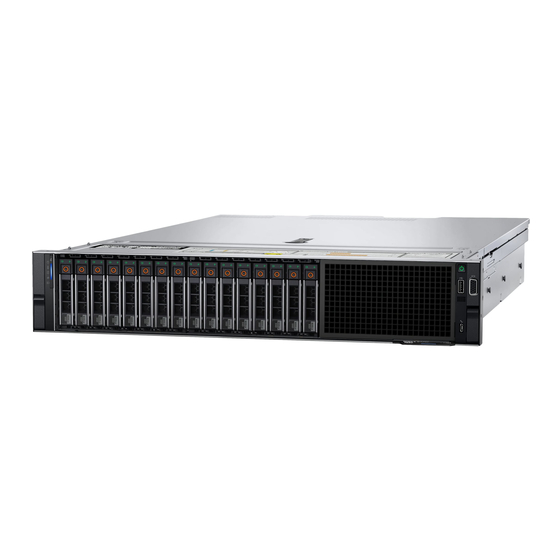
● 8 x 3.5-inch SAS/ SATA drives NOTE: All instances of SAS, SATA drives are referred to as drives in this document, unless specified otherwise. NOTE: For more information, see the Dell EMC PowerEdge R550 Technical Specifications on the product documentation page. Topics: •... - Page 9 For more information, see the iDRAC User's Guide available at https://www.dell.com/ idracmanuals Drive Enables you to install drives that are supported on your system.
- Page 10 For more information, see the iDRAC User's Guide available at https://www.dell.com/ idracmanuals Optical drive blank For the 8 x 3.5-inch drive system, a optical drive bay blank is installed.
-
Page 11: Left Control Panel View
Information tag also contains the iDRAC secure default password. NOTE: For more information, see the Dell EMC PowerEdge R550 Technical Specifications on the product documentation page. Left control panel view Figure 4. Left control panel without optional iDRAC Quick Sync 2 indicator Table 4. -
Page 12: Right Control Panel View
3 feet (0.91 meters). Performance could be affected by cable quality. VGA port Enables you to connect a display device to the system. NOTE: For more information, see the Dell EMC PowerEdge R550 Technical Specifications on the product documentation page. System overview... -
Page 13: Rear View Of The System
Enables you to remotely access iDRAC. For more information, see the iDRAC User's Guide at www.dell.com/poweredgemanuals NIC ports (1, 2) The NIC ports are embedded on the LOM card that is connected to the system board to provide network connectivity. These NIC ports... -
Page 14: Inside The System
NOTE: For more information, see the Dell EMC PowerEdge R550 Technical Specifications on the product documentation page. Inside the system Figure 8. Inside the system 1. -
Page 15: System Information Label
The Mini Enterprise Service Tag (MEST) label is located on the rear of the system that includes the Service Tag (ST), Express Service Code (Exp Svc Code), and Manufacture Date (Mfg. Date). The Exp Svc Code is used by Dell EMC to route support calls to the appropriate personnel. - Page 16 Figure 10. Service information System overview...
- Page 17 Figure 11. Service information System overview...
- Page 18 Figure 12. Memory information Figure 13. Configuration and layout System overview...
- Page 19 Figure 14. Configuration and layout Figure 15. LED behavior System overview...
- Page 20 Figure 16. System tasks System overview...
-
Page 21: Rail Sizing And Rack Compatibility Matrix
Figure 17. Express service tag Rail sizing and rack compatibility matrix For specific information about the rail solutions compatible with your system, see the Dell EMC Enterprise Systems Rail Sizing and Rack Compatibility Matrix available at https://i.dell.com/sites/csdocuments/Business_solutions_engineering- Docs_Documents/en/rail-rack-matrix.pdf. The document provides the information that is listed below: ●... -
Page 22: Chapter 3: Initial System Setup And Configuration
Initial system setup and configuration This section describes the tasks for initial setup and configuration of the Dell EMC system. The section also provides general steps to set up the system and the reference guides for detailed information. Topics: •... -
Page 23: Options To Log In To Idrac
OpenManage Deployment Toolkit OpenManage Deployment Toolkit User's Guide available at https://www.dell.com/openmanagemanuals > Open Manage Deployment Toolkit. iDRAC Direct Integrated Dell Remote Access Controller User's Guide at https://www.dell.com/idracmanuals or for system specific Integrated Dell Remote Access Controller User's Guide, go to https://www.dell.com/poweredgemanuals >... -
Page 24: Resources To Install Operating System
For more information about logging in to the iDRAC and iDRAC licenses, see the latest Integrated Dell Remote Access Controller User's Guide at www.dell.com/idracmanuals. NOTE: To determine the most recent iDRAC release for your platform and for latest documentation version, see KB article https://www.dell.com/support/article/sln308699. -
Page 25: Options To Download And Install Os Drivers
Ensure that you clear the web browser cache before downloading the drivers and firmware. Steps 1. Go to www.dell.com/support/drivers. 2. Enter the Service Tag of the system in the Enter a Dell Service Tag, Dell EMC Product ID or Model field, and then press Enter. NOTE: If you do not have the Service Tag, click Browse all products, and navigate to your product. -
Page 26: Chapter 4: Minimum To Post And System Management Configuration Validation
Minimum to POST and system management configuration validation This section describes the minimum to POST system requirement and system management configuration validation of the Dell EMC system. Topics: • Minimum configuration to POST • Configuration validation Minimum configuration to POST The components listed below are the minimum configuration to POST: ●... -
Page 27: Error Messages
Table 12. Configuration validation error (continued) Error Description Possible cause and Example recommendations Comm Error A configuration element is not responding System management Comm Error: Backplane 2 to iDRAC using the management interface sideband communication while running an inventory check. Unplug AC Power, reseat the element and replace the element if the problem... -
Page 28: Chapter 5: Installing And Removing System Components
Installing and removing system components Topics: • Safety instructions • Before working inside your system • After working inside your system • Recommended tools • Optional front bezel • System cover • Drive backplane cover • Air shroud • Cooling fans •... -
Page 29: Before Working Inside Your System
Damage due to servicing that is not authorized by Dell is not covered by your warranty. Read and follow the safety instructions that are shipped with your product. -
Page 30: Optional Front Bezel
● Wrist grounding strap connected to the ground ● ESD mat You need the following tools to assemble the cables for a DC power supply unit: ● AMP 90871-1 hand-crimping tool or equivalent ● Tyco Electronics 58433-3 or equivalent ● Wire-stripper pliers to remove insulation from size 10 AWG solid or stranded, insulated copper wire NOTE: Use alpha wire part number 3080 or equivalent (65/30 stranding). -
Page 31: Installing The Front Bezel
Next steps Replace the front bezel. Installing the front bezel The procedure to install the front bezel with and without the LCD panel is the same. Prerequisites 1. Follow the safety guidelines listed in the Safety instructions. 2. Locate and remove the bezel key. NOTE: The bezel key is part of the LCD bezel package. -
Page 32: Installing The System Cover
Steps 1. Using a 1/4-inch flat head or Phillips #2 screwdriver, rotate the lock counterclockwise to the unlock position. 2. Lift the release latch until the system cover slides back. 3. Lift the cover from the system. Figure 20. Removing the system cover Next steps Replace the system cover. -
Page 33: Drive Backplane Cover
Figure 21. Installing the system cover Next steps Follow the procedure listed in After working inside your system. Drive backplane cover Removing the drive backplane cover Prerequisites 1. Follow the safety guidelines listed in the Safety instructions. 2. Follow the procedure listed in the Before working inside your system. -
Page 34: Installing The Drive Backplane Cover
Figure 22. Removing the drive backplane cover Next steps Replace the drive backplane cover. Installing the drive backplane cover Prerequisites 1. Follow the safety guidelines listed in the Safety instructions. 2. Follow the procedure listed in the Before working inside your system. - Page 35 Figure 23. Installing the drive backplane cover Next steps Follow the procedure listed in After working inside your system. Installing and removing system components...
-
Page 36: Air Shroud
Air shroud Removing the air shroud Prerequisites CAUTION: Never operate your system with the air shroud removed. The system may get overheated quickly, resulting in shutdown of the system and loss of data. 1. Follow the safety guidelines listed in the Safety instructions. -
Page 37: Cooling Fans
Figure 25. Installing the air shroud Next steps Follow the procedure listed in After working inside your system. Cooling fans Removing the cooling fan cage assembly Prerequisites 1. Follow the safety guidelines listed in the Safety instructions. 2. Follow the procedure listed in the Before working inside your system. -
Page 38: Installing The Cooling Fan Cage Assembly
Figure 26. Removing the cooling fan cage assembly Next steps Replace the cooling fan cage. Installing the cooling fan cage assembly Prerequisites 1. Follow the safety guidelines listed in the Safety instructions. CAUTION: Ensure that the cables inside the system are correctly installed and retained by the cable retention bracket before installing the cooling fan cage assembly. -
Page 39: Removing A Cooling Fan
Figure 27. Installing the cooling fan cage assembly Next steps 1. If removed, Install the air shroud. 2. Follow the procedure listed in After working inside your system. Removing a cooling fan Prerequisites 1. Follow the safety guidelines listed in the Safety instructions. -
Page 40: Installing A Cooling Fan
Figure 28. Removing a cooling fan Next steps Replace the cooling fan. Installing a cooling fan Prerequisites 1. Follow the safety guidelines listed in the Safety instructions. 2. Follow the procedure listed in the Before working inside your system. Steps Align and slide the cooling fan into the cooling fan cage until the fan clicks into place. -
Page 41: Side Wall Brackets
Figure 29. Installing a cooling fan Next steps Follow the procedure listed in After working inside your system. Side wall brackets Removing the side wall bracket There are two side wall brackets on either side of the system. The procedure to remove is similar. Prerequisites 1. -
Page 42: Installing The Side Wall Bracket
Figure 30. Removing the side wall bracket Next steps Replace the side wall bracket. Installing the side wall bracket There are two side wall brackets on either side of the system. The procedure to install is similar. Prerequisites 1. Follow the safety guidelines listed in the Safety instructions. -
Page 43: Intrusion Switch Module
Figure 31. Installing the side wall bracket Next steps Install the air shroud. Install the cooling fan cage assembly 3. Follow the procedure listed in the After working inside your system. Intrusion switch module This is a service technician replaceable part only. Removing the intrusion switch module Prerequisites 1. -
Page 44: Installing The Intrusion Switch Module
3. Lift the intrusion switch module out of the system. Figure 32. Removing the intrusion switch module Next steps Replace the intrusion switch module. Installing the intrusion switch module Prerequisites 1. Follow the safety guidelines listed in the Safety instructions. 2. -
Page 45: Optional Serial Com Port
Figure 33. Installing the intrusion switch Next steps 1. Connect the system power cable to the system board. Install the air shroud. 3. Follow the procedure listed in After working inside your system. Optional serial COM port This is a service technician replaceable part only. Removing the optional serial COM port Prerequisites 1. -
Page 46: Installing The Optional Serial Com Port
Figure 34. Removing the Serial COM port 3. Install the filler bracket if not replacing the serial COM port. Next steps Replace the serial COM port. Installing the optional serial COM port Prerequisites 1. Follow the safety guidelines listed in the Safety instructions. -
Page 47: Drives
Figure 35. Installing the Serial COM port Next steps 1. Follow the procedure listed in After working inside your system. Drives Removing a drive blank Prerequisites 1. Follow the safety guidelines listed in the Safety instructions. 2. If installed, remove the front bezel. -
Page 48: Installing A Drive Blank
Next steps Installing a drive replace the drive blank. Installing a drive blank Prerequisites 1. Follow the safety guidelines listed in the Safety instructions. 2. If installed, remove the front bezel. Steps Insert the drive blank into the drive slot until the release button clicks into place. Figure 37. -
Page 49: Installing The Drive Carrier
Figure 38. Removing a drive carrier Next steps Install a drive carrier install a drive blank. Installing the drive carrier Prerequisites CAUTION: Before removing or installing a drive while the system is running, see the documentation for the storage controller card to ensure that the host adapter is configured correctly to support drive removal and insertion. -
Page 50: Removing The Drive From The Drive Carrier
Figure 39. Installing a drive carrier Next steps If removed, install the front bezel. Removing the drive from the drive carrier Prerequisites 1. Follow the safety guidelines listed in the Safety instructions. Remove the drive carrier Steps 1. Using a Phillips #1 screwdriver, remove the screws from the slide rails on the drive carrier. NOTE: If the drive or SSD carrier has Torx screw, use Torx 6 (for 2.5-inch drive) or Torx 8 (for 3.5-inch drive) screwdriver to remove the drive. -
Page 51: Installing The Drive Into The Drive Carrier
Figure 40. Removing the drive from the drive carrier Next steps Install the drive into the drive carrier. Installing the drive into the drive carrier Prerequisites 1. Follow the safety guidelines listed in the Safety instructions. Remove the drive carrier Steps 1. -
Page 52: Drive Backplane
Figure 41. Installing a drive into the drive carrier Next steps Install the drive carrier. Drive backplane This is a service technician replaceable part only. Drive backplane Depending on your system configuration, the drive backplanes supported are listed here: Table 15. Supported backplane options System Supported drives options 16 x 2.5-inch SAS/SATA backplane... -
Page 53: Removing The Drive Backplane
4. BP_PWR_1 (backplane power to system board) Figure 43. 8 x 2.5-inch drive backplane 1. BP_PWR_CTRL 2. BP_DST_SA1 (PERC to backplane) 3. BP_DST_PA1 (PCIe connector) 4. BP_ DST_PB1 (PCIe connector) 5. BP_ DST_PA2 (PCIe connector) 6. BP_PWR_1 (backplane power and signal cable to system board) 7. -
Page 54: Installing The Drive Backplane
Steps 1. Press the blue release tabs to disengage the drive backplane from the hooks on the system. 2. Lift the drive backplane out of the system. NOTE: To avoid damaging the backplane, ensure that you move the control panel cables from the cable routing clips before removing the backplane. - Page 55 Figure 46. Installing the drive backplane Next steps 1. If removed, connect the optical drive signal and power cables to the system. 2. Connect the drive backplane cables to the connectors on the system board. Install the drives. Install the PERC card.
-
Page 56: Cable Routing
Cable routing Figure 47. 8 x 2.5-inch SAS/SATA Table 16. 8 x 2.5-inch SAS/SATA From CTRL_DST_PA1 (Signal connector on the front PERC) SL3_CPU1_PB2 (Signal connector on system board) BP_PWR_1 (Power connector on backplane) SIG_PWR_3 (Power connector on system board) BOSS_PWR (BOSS card power connector) BOSS_PWR (Power connector for BOSS card on system board) SL10_PCH_PA5 (BOSS signal connector on system board) - Page 57 Table 17. 8 x 3.5-inch SAS/SATA From CTRL_DST_PA1 (Signal connector on the front PERC) SL3_CPU1_PB2 (Signal connector on system board) BP_PWR_1 (Power connector on backplane) SIG_PWR_3 (Power connector on system board) BOSS_PWR (BOSS card power connector) BOSS_PWR (Power connector for BOSS card on system board) SL10_PCH_PA5 (BOSS signal connector on system board) BOSS signal on BOSS S2 card module...
- Page 58 Figure 50. ODD and no PERC configuration Table 19. ODD and no PERC configuration From CTRL_SRC_SB1 (Signal connector on the front PERC) BP_DST_SB1 (Signal connector on backplane) CTRL_DST_SA1 (Signal connector on the drive backplane) SL9_PCH_SA1 (Signal connector on system board) ODD (Optical Disk Drive connector on system board) ODD (Optical Disk Drive) ODD_PWR_1 (ODD card power connector)
-
Page 59: System Memory
Figure 51. VGA and Control Panel Table 20. VGA and Control Panel From LEFT_CP (Left control panel connector) Left control panel (LCP) RGT_CP (Right control panel connector) Right control panel (RCP) FRONT_VIDEO (Front VGA connector) VGA on RCP System memory System memory guidelines The PowerEdge R550 system supports DDR4 registered DIMMs (RDIMMs). -
Page 60: General Memory Module Installation Guidelines
Figure 52. Memory channels Table 22. Supported memory matrix DIMM type Rank Capacity DIMM rated voltage and speed Operating speed for DIMMs per Channel (DPC) RDIMM 8 GB DDR4 (1.2V), 3200 MT/s 2933 MT/s 16 GB, 32 GB, 64 GB DDR4 (1.2V), 3200 MT/s 2933 MT/s General memory module installation guidelines... -
Page 61: Removing A Memory Module
● In Optimizer Mode, the DRAM controllers operate independently in the 64-bit mode and provide optimized memory performance. Table 23. Memory population rules Processor Configuration Memory population Memory population information Single processor Optimizer (Independent A{1}, A{2}, A{3}, A{4}, A{5}, A{6}, 1, 2, 3, 4 DIMMs are channel) population order A{7}, A{8}... -
Page 62: Installing A Memory Module
Figure 53. Removing a memory module Next steps Replace the memory module. Installing a memory module Prerequisites 1. Follow the safety guidelines listed in the Safety instructions. 2. Follow the procedure listed in the Before working inside your system. Remove the air shroud. -
Page 63: Processor And Heat Sink Module
4. Press the memory module with your thumbs until the ejectors firmly click into place. When the memory module is properly seated in the socket, the levers on the memory module socket align with the levers on the other sockets that have memory modules installed. - Page 64 a. Loosen the first nut three turns. b. Loosen the nut diagonally opposite to the nut you loosened first. c. Repeat the procedure for the remaining two nuts. d. Return to the first nut to loosen it completely. 2. Set all the anti-tilt wires to unlocked position (inward position). Figure 55.
-
Page 65: Removing The Processor From The Processor And Heat Sink Module
Next steps If you are removing a faulty heat sink, replace the heat sink, if not, remove the processor. Removing the processor from the processor and heat sink module Prerequisites WARNING: The heat sink may be hot to touch for some time after the system has been powered off. Allow the heat sink to cool before removing it. - Page 66 Figure 58. Aligning pin 1 marks of processor with tray NOTE: Ensure to return the TIM break lever back to original position. 4. Using your thumb and index finger, first hold the retaining clip release tab at the pin 1 connector, pull out the tip of the retaining clip release tab, and then lift the retaining clip partially from the heat sink.
-
Page 67: Installing The Processor Into A Processor And Heat Sink Module
Figure 59. Removing the retaining clip Next steps Replace the processor into a processor and heat sink module (PHM). Installing the processor into a processor and heat sink module Prerequisites 1. Follow the safety guidelines listed in the Safety instructions. 2. - Page 68 Figure 60. Installing the processor bracket 3. Align the processor with retaining clip, by using the fingers press the retaining clip on all the four sides until it clicks into place. NOTE: Ensure the processor is securely latched to the retaining clip. Figure 61.
- Page 69 CAUTION: Applying too much thermal grease can result in excess grease coming in contact with and contaminating the processor socket. NOTE: The thermal grease syringe is intended for single use only. Dispose the syringe after you use it. Figure 62. Applying thermal grease 6.
- Page 70 Figure 63. Remove the Thermal Interface Material (TIM) protective film 7. Place the heat sink on the processor and press the base of the heat sink until the retaining clip locks onto the heat sink at all the four corners. CAUTION: To avoid damaging the fins on the heat sink, do not press down on the heat sink fins.
-
Page 71: Installing The Processor Heat Sink Module
Figure 64. Installing the heat sink onto the processor Next steps Install the processor and heat sink module. Install the air shroud. 3. Follow the procedure listed in After working inside your system. Installing the processor heat sink module Prerequisites Never remove the heat sink from a processor unless you intend to replace the processor or system board. - Page 72 Figure 65. Installing the processor heat sink module 3. Set the anti-tilt wires to the locked position (outward position), and then using the Torx #T30 tool, tighten the captive nuts (8 in-lbf) on the PHM in the order below: a. In a random order, tighten the first nut three turns. b.
-
Page 73: Expansion Cards And Expansion Card Risers
A system event entry is logged in the iDRAC Lifecycle Controller if an expansion card riser is not supported or missing. It does not prevent your system from turning on. However, if a F1/F2 pause occurs with an error message, see Troubleshooting expansion cards section in the Dell EMC PowerEdge Servers Troubleshooting Guide at www.dell.com/ poweredgemanuals. -
Page 74: Expansion Card Installation Guidelines
Expansion card installation guidelines Figure 67. Expansion card slot connectors 1. Slot 1 2. Slot 2 3. Slot 5 4. Slot 6 The following table describes the expansion card configurations: Table 24. Supported configurations Configurations Expansion card PCIe Slots Controlling Height Length Slot width... - Page 75 Table 25. Configuration 0 Card type Slot priority Maximum number of cards Dell Serial port module (LP) fPERC Integrated slot Internal PERC adapter 12Gbps SAS HBA Intel (NIC: 100Gb) 5, 6, 1 Mellanox (NIC: 100Gb) 5, 6, 1 Broadcom (NIC: 25Gb)
-
Page 76: Removing The Expansion Card
Integrated slot Intel (OCP: 10Gb) Integrated slot Broadcom (OCP: 1Gb) Integrated slot Intel (OCP: 1Gb) Integrated slot Dell External PERC Adapter 1, 2 Dell BOSS S1 Module Integrated slot Samsung (PCIe SSD AIC) 1, 2 Intel (PCIe SSD) Not supported... - Page 77 2. Disconnect the cables form the expansion card. 3. By holding the edges lift the expansion card from the PCIe slot on the system board Figure 68. Removing the expansion card 4. Install the metal filler bracket if not replacing the expansion card. NOTE: The numbers on the image do not depict the exact steps.
-
Page 78: Installing The Expansion Card
Installing the expansion card Prerequisites 1. Follow the safety guidelines listed in the Safety instructions. 2. Follow the procedure listed in the Before working inside your system. 3. If required, remove the air shroud. Steps 1. Rotate to open the PCIe card holder. 2. -
Page 79: Optional Idsdm Module
Figure 71. Installing the expansion card Next steps 1. If removed, install the air shroud. 2. Follow the procedure listed in After working inside your system. Optional IDSDM module Removing the IDSDM module Prerequisites 1. Follow the safety guidelines listed in the Safety instructions. -
Page 80: Installing The Idsdm Module
Figure 72. Removing the IDSDM module Next steps Replace the IDSDM module. Installing the IDSDM module Prerequisites 1. Follow the safety guidelines listed in the Safety instructions. 2. Follow the procedure listed in the Before working inside your system. Steps 1. -
Page 81: Optional Boss S2 Card
Figure 73. Installing the IDSDM module Next steps Install the MicroSD cards. NOTE: Reinstall the MicroSD cards into the same slots based on the labels you had marked on the cards during removal. 2. Follow the procedure listed in the After working inside your system. - Page 82 Figure 74. Removing the BOSS S2 card carrier 3. Using the Phillips #1 screwdriver remove the M3 x 0.5 x 4.5 mm screw that secures the M.2 SSD to the BOSS S2 card carrier. 4. Slide the M.2 SSD out from the BOSS S2 card carrier. Figure 75.
- Page 83 Figure 76. Removing the BOSS S2 module 8. Remove the BOSS power cable and BOSS signal cable from the BOSS S2 controller card module. Figure 77. Removing the BOSS power cable and BOSS signal cable 9. Using the Phillips #1 screwdriver, remove the M3 x 0.5 x 4.5 mm screw that secures the BOSS cover on the BOSS S2 module.
-
Page 84: Installing The Boss S2 Module
Figure 78. Removing the BOSS cover Next steps Replace the BOSS S2 module. Installing the BOSS S2 module Prerequisites 1. Follow the safety guidelines listed in the Safety instructions. 2. Follow the procedure listed in the Before working inside your system. - Page 85 Figure 79. Installing the BOSS cover 2. Connect the BOSS power cable and BOSS signal cable to the BOSS S2 module. Figure 80. Connecting the BOSS power cable and BOSS Signal cable to the BOSS S2 module 3. Slide the BOSS S2 module into the BOSS module bay until it is firmly seated. 4.
- Page 86 Figure 81. Installing the BOSS S2 module 6. Align the M.2 SSD at an angle with the BOSS S2 card carrier. 7. Insert the M.2 SSD until it is firmly seated in the BOSS S2 card carrier. 8. Using the Phillips #1 screwdriver, secure the M.2 SSD on the BOSS S2 card carrier with the M3 x 0.5 x 4.5 mm screw. Figure 82.
-
Page 87: Front Mounting Front Perc Module
Figure 83. Installing the BOSS S2 card carrier Next steps 1. If removed, install the air shroud. 2. Follow the procedure listed in the After working inside your system. Front mounting front PERC module This is a service technician replaceable part only. Removing the front mounting front PERC module Prerequisites 1. -
Page 88: Installing The Front Mounting Front Perc Module
Figure 84. Removing the front mounting front PERC module Next steps Replace the front mounting front PERC module. Installing the front mounting front PERC module Prerequisites 1. Follow the safety guidelines listed in the Safety instructions. 2. Follow the procedure listed in the Before working inside your system. -
Page 89: Optional Ocp Card
Figure 85. Installing the front mounting front PERC module Next steps 1. Connect the PERC cables to the backplane and system board connectors. Install the cooling fan cage assembly. Install the drive backplane cover. Install the air shroud. 5. Follow the procedure listed in After working inside your system. -
Page 90: Installing The Ocp Shroud
Figure 86. Removing the OCP shroud Next steps Replace the OCP shroud. Installing the OCP shroud Prerequisites 1. Follow the safety guidelines listed in the Safety instructions. 2. Follow the procedure listed in the Before working inside your system. Steps 1. -
Page 91: Removing The Ocp Card
Next steps 1. Follow the procedure listed in After working inside your system. Removing the OCP card Prerequisites 1. Follow the safety guidelines listed in the Safety instructions. 2. Follow the procedure listed in the Before working inside your system. Remove the OCP shroud. -
Page 92: Installing The Ocp Card
Figure 88. Removing the OCP card 4. If the OCP card is not going to be replaced, install a filler bracket. Next steps Replace the OCP card. Installing the OCP card Prerequisites 1. Follow the safety guidelines listed in the Safety instructions. -
Page 93: System Battery
Next steps Install the OCP shroud. 2. Follow the procedure listed in After working inside your system. System battery This is a service technician replaceable part only. Replacing the system battery Prerequisites WARNING: There is a danger of a new battery exploding if it is incorrectly installed. Replace the battery only with the same or equivalent type recommended by the manufacturer. - Page 94 Figure 90. Removing the system battery CAUTION: To avoid damage to the battery connector, you must firmly support the connector while installing or removing a battery. 2. To install a new system battery: a. Hold the battery with the positive side facing up and slide it under the securing tabs. b.
-
Page 95: Optional Internal Usb Key
a. Enter the System Setup, while booting, by pressing F2. b. Enter the correct time and date in the System Setup Time and Date fields. c. Exit the System Setup. d. To test the newly installed battery, remove the system from the enclosure for at least an hour. e. -
Page 96: Microsd Card
2. Follow the procedure listed in the Before working inside your system. Steps 1. Connect the USB key to the internal USB card. NOTE: For information on the exact location of USB on system board, see System board jumpers and connectors section 2. -
Page 97: Installing The Microsd Card
Figure 94. Removing the MicroSD card Next steps Replace the MicroSD cards. Installing the MicroSD card Prerequisites 1. Follow the safety guidelines listed in the Safety instructions. 2. Follow the procedure listed in Before working inside your system. NOTE: To use an MicroSD card with your system, ensure that the Internal SD Card Port is enabled in System Setup. NOTE: Ensure that you install the MicroSD cards into the same slots based on the labels you had marked on the cards during removal. -
Page 98: Power Supply Unit
● If the load on the active PSU falls below 20 percent of PSU rated power wattage, then the redundant PSU is switched to the sleep state. You can configure the hot spare feature by using the iDRAC settings. For more information, see the iDRAC User’s Guide available at www.dell.com/poweredgemanuals. Removing a power supply unit blank Prerequisites... -
Page 99: Installing A Power Supply Unit Blank
Steps Pull the blank out of the system. CAUTION: To ensure proper system cooling, the PSU blank must be installed in the second PSU bay in a non-redundant configuration. Remove the PSU blank only if you are installing a second PSU. Figure 96. -
Page 100: Removing A Power Supply Unit
3. Remove the cable from the strap on the PSU handle. 4. Unlatch and lift the optional cable management arm if it interferes with the PSU removal. For information about the cable management arm, see the system’s rack documentation at https://www.dell.com/ poweredgemanuals. Steps Press the orange release latch, and holding the PSU handle slide the PSU out of the PSU bay. -
Page 101: Power Interposer Board
1. If you have unlatched the cable management arm, relatch it. For information about the cable management arm, see the system’s rack documentation at https://www.dell.com/poweredgemanuals. 2. Connect the power cable to the PSU, and plug the cable into a power outlet. -
Page 102: Installing The Power Interposer Board
Figure 100. Removing the power interposer board Next steps Replace the power interposer board. Installing the power interposer board Prerequisites 1. Follow the safety guidelines listed in the Safety instructions. 2. Follow the procedure listed in the Before working inside your system. -
Page 103: Cooling Fan Cage Board
Figure 101. Installing the power interposer board Next steps 1. Connect the cables to the PIB and route them properly. Install the PSU. Install the air shroud. 4. Follow the procedure listed in After working inside your system. Cooling fan cage board Removing the cooling fan cage board Prerequisites 1. -
Page 104: Installing The Cooling Fan Cage Board
Figure 102. Removing the cooling fan cage board. Next steps Replace the cooling fan cage board. Installing the cooling fan cage board Prerequisites 1. Follow the safety guidelines listed in the Safety instructions. 2. Follow the procedure listed in Before working inside your system. -
Page 105: System Board
Figure 103. Installing the cooling fan cage board Next steps 1. Connect cables to the fan board. 2. Replace the following components: Cooling fan cage assembly Air shroud 3. Follow the procedure listed in After working inside your system. System board This is a service technician replaceable part only. -
Page 106: Installing The System Board
OCP shroud Disconnect all cables from the system board. CAUTION: Take care not to damage the system identification button while removing the system board from the system. Steps 1. Using the system board holder and plunger, slide the system board toward the front of the chassis. 2. - Page 107 CAUTION: Take care not to damage the system identification button while placing the system board into the chassis. 2. Using the system board holder and plunger , lower the system board leaning at an angle into the system. 3. Slide the system board towards the rear of the chassis until the connectors are firmly seated in the slots. Figure 105.
-
Page 108: Restoring The System Using Easy Restore
4. If you are not using Easy restore, import your new or existing iDRAC Enterprise license. For more information, see the iDRAC User's Guide available at https://www.dell.com/idracmanuals 5. Follow the procedure listed in After working inside your system. Restoring the system using Easy Restore The Easy Restore feature enables you to restore your service tag, license, UEFI configuration, and the system configuration data after replacing the system board. -
Page 109: Initializing Tpm For Users
About this task CAUTION: After the TPM plug-in module is installed, it is cryptographically bound to that specific system board. When the system is powered on, any attempt to remove an installed TPM plug-in module breaks the cryptographic binding, and the removed TPM cannot be installed on another system board. Ensure any keys you have stored on the TPM have been securely transferred. -
Page 110: Initializing The Tpm 2.0 For Users
3. From the TPM Security option, select On with Preboot Measurements. 4. From the TPM Command option, select Activate. 5. Save the settings. 6. Restart your system. Initializing the TPM 2.0 for users Steps 1. While booting your system, press F2 to enter System Setup. 2. -
Page 111: Installing The Left Control Panel
Figure 107. Removing the left control panel Next steps Replace the left control panel. Installing the left control panel Prerequisites 1. Follow the safety guidelines listed in the Safety instructions. 2. Follow the procedure listed in the Before working inside your system. -
Page 112: Removing The Right Control Panel
Next steps Install the cooling fan cage assembly. Install the drive backplane cover. Install the air shroud. 4. Follow the procedure listed in the After working inside your system. Removing the right control panel Prerequisites 1. Follow the safety guidelines listed in the Safety instructions. -
Page 113: Installing The Right Control Panel
Figure 109. Removing the right control panel Next steps Replace the right control panel. Installing the right control panel Prerequisites 1. Follow the safety guidelines listed in the Safety instructions. 2. Follow the procedure listed in the Before working inside your system. -
Page 114: Optional Optical Drive
Figure 110. Installing the right control panel Next steps Install the cooling fan cage assembly. Install the drive backplane cover. Install the air shroud. 4. Follow the procedure listed in the After working inside your system. Optional optical drive This is a service technician replaceable part only. Removing the optical disk drive Prerequisites 1. -
Page 115: Installing The Optical Disk Drive
Figure 111. Removing the ODD Next steps Replace the ODD. Installing the optical disk drive Prerequisites 1. Follow the safety guidelines listed in the Safety instructions. 2. Follow the procedure listed in the Before working inside your system. Remove the air shroud. - Page 116 Figure 112. Installing the ODD Next steps 1. Connect the power and signal cables to the ODD and system board connector. Route the cables though the side wall bracket. Install the drive backplane cover. Install the air shroud. 4. Follow the procedure listed in After working inside your system.
-
Page 117: Chapter 6: Jumpers And Connectors
Jumpers and connectors This section provides essential and specific information about jumpers and switches. It also describes the connectors on the various boards in the system. Jumpers on the system board help to disable the system and reset the passwords. To install components and cables correctly, you must be able to identify the connectors on the system board. -
Page 118: System Board Jumper Settings
Table 27. System board jumpers and connectors (continued) Item Connector Description x16 (CPU2) PCIe slot 5 ( Processor 2) Coin cell battery Coin cell battery OCP 3.0 x16 OCP NIC 3.0 Connector J_TPM TPM Connector IDSDM/Internal USB connector IDSDM/Internal USB connector REAR_SERIAL Serial Port Connector x4 (PCH) -
Page 119: Disabling A Forgotten Password
Damage due to servicing that is not authorized by Dell is not covered by your warranty. Read and follow the safety instructions that are shipped with your product. -
Page 120: Chapter 7: System Diagnostics And Indicator Codes
System diagnostics and indicator codes This section describes the diagnostic indicators on the system front panel that displays the system status during system startup. Topics: • Status LED indicators • System health and system ID indicator codes • iDRAC Quick Sync 2 indicator codes •... -
Page 121: System Health And System Id Indicator Codes
For information about the event and error messages generated by the system firmware and agents that monitor system components, go qrl.dell.com > Look Up > Error Code, type the error code, and then click Look it... -
Page 122: Idrac Quick Sync 2 Indicator Codes
If the problem persists, see the Getting help section. www.dell.com/poweredgemanuals or Dell OpenManage Server Administrator User’s Guide at https://www.dell.com/openmanagemanuals. Solid amber Indicates that the system is in fail-safe Restart the system. If the problem persists, see mode. -
Page 123: Lcd Panel
The LCD panel is used to configure or view the iDRAC IP address of the system. For information about the event and error messages generated by the system firmware and agents that monitor system components, go to qrl.dell.com >... -
Page 124: Viewing Home Screen
For information about the event and error messages generated by the system firmware and agents that monitor system components, go to qrl.dell.com > Look Up > Error Code, type the error code, and then click Look it up.. -
Page 125: Nic Indicator Codes
NIC indicator codes Each NIC on the back of the system has indicators that provide information about the activity and link status. The activity LED indicator indicates if data is flowing through the NIC, and the link LED indicator indicates the speed of the connected network. Figure 117. - Page 126 Table 37. AC PSU status indicator codes Power indicator codes Condition Green Indicates that a valid power source is connected to the PSU and the PSU is operational. Blinking amber Indicates an issue with the PSU. Not powered on Indicates that the power is not connected to the PSU. Blinking green Indicates that the firmware of the PSU is being updated.
-
Page 127: Drive Indicator Codes
Table 38. DC PSU status indicator codes (continued) Power indicator codes Condition same power rating. This results in a PSU mismatch condition, or failure to power on the system. CAUTION: If two PSUs are used, they must be of the same type and have the same maximum output power. -
Page 128: Using System Diagnostics
Using system diagnostics If you experience an issue with the system, run the system diagnostics before contacting Dell for technical assistance. The purpose of running system diagnostics is to test the system hardware without using additional equipment or risking data loss. - Page 129 The ePSA Pre-boot System Assessment window is displayed, listing all devices detected in the system. The diagnostics starts executing the tests on all the detected devices. System diagnostic controls Table 40. System diagnostic controls Menu Description Configuration Displays the configuration and status information of all detected devices.
-
Page 130: Chapter 8: Getting Help
Dell contact information on your purchase invoice, packing slip, bill or Dell product catalog. The availability of services varies depending on the country and product, and some services may not be available in your area. To contact Dell for sales, technical... -
Page 131: Quick Resource Locator For Poweredge R550 System
Dell EMC. This information is used by Dell EMC Technical Support to troubleshoot the issue. ● Proactive contact — A Dell EMC Technical Support agent contacts you about the support case and helps you resolve the issue. -
Page 132: Chapter 9: Documentation Resources
This section provides information about the documentation resources for your system. To view the document that is listed in the documentation resources table: ● From the Dell EMC support site: 1. Click the documentation link that is provided in the Location column in the table. - Page 133 Methods to download firmware and drivers section in this document. Managing your system For information about systems management www.dell.com/poweredgemanuals software offered by Dell, see the Dell OpenManage Systems Management Overview Guide. For information about setting up, using, www.dell.com/openmanagemanuals >...
Need help?
Do you have a question about the 8TTX3 and is the answer not in the manual?
Questions and answers