
Related Manuals for GIGA-BYTE TECHNOLOGY GA-7PTSH


Summary of Contents for GIGA-BYTE TECHNOLOGY GA-7PTSH
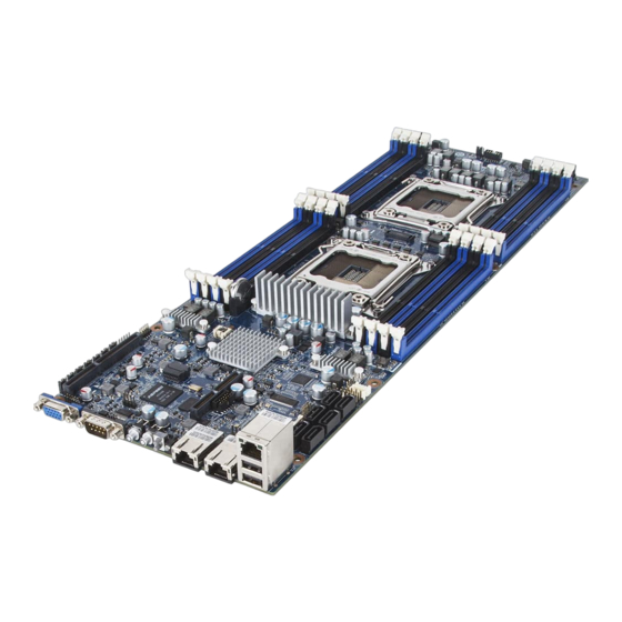
- Page 1 GA-7PTSH E5-2600 Dual LGA2011 sockets motherboard for Intel series processors ® User's Manual Rev. 1001...
- Page 2 Copyright © 2013 GIGA-BYTE TECHNOLOGY CO., LTD. All rights reserved. The trademarks mentioned in this manual are legally registered to their respective owners. Disclaimer Information in this manual is protected by copyright laws and is the property of GIGABYTE. Changes to the specifications and features in this manual may be made by GIGABYTE without prior notice.
-
Page 3: Table Of Contents
Table of Contents Box Contents ........................5 GA-7PTSH Motherboard Layout ..................6 Chapter 1 Hardware Installation ..................8 Installation Precautions ..................8 1-2 Product Specifications ..................9 Installing the CPU ..................11 1-3-1 Installing the CPU ....................11 Installing the Memory ..................13 1-4-1 Four Channel Memory Configuration ..............13 1-4-2 Installing a Memory ....................14... - Page 4 2-3-3 Intel ME Subsystem ....................70 Security Menu ....................71 Server Management Menu ................72 2-5-1 BMC LAN Configuration ..................73 2-5-2 BMC Function ......................74 2-5-3 View FRU Information ....................75 2-5-4 System Event Log ....................76 Boot Menu ..................... 77 2-6-1 CSM16 Parameters ....................79 2-6-2 CSM Parameters ....................80 Exit Menu .......................
-
Page 5: Box Contents
Box Contents Motherboard Driver CD Two SATA cables • The box contents above are for reference only and the actual items shall depend on the product package you obtain. The box contents are subject to change without notice. • The motherboard image is for reference only. - 5 -... -
Page 6: Ga-7Ptsh Motherboard Layout
GA-7PTSH Motherboard Layout Item Code Description FP_VGA1 Front VGA header VGA1 Rear VGA port COM2 Serial port cable header COM1 Serial port ASPEED 2300 BMC chipset BMC_LED1 BMC readiness LED PCIE_2 PCI-E slot 2 (x8 slot/Proprietary/Running at x8) PWR_SW Power swith button... - Page 7 DDR3_P1_G0 Channel 3 slot 0 (for secondary CPU) SSI_2X9P2 18 pin power connector (for secondary CPU) F_PANEL Front panel header ACK_SEL 4 Nodes System and Rack System switch jumper SSI_2X9P1 18 pin power connector (for primary CPU) DDR3_P1_F1 Channel 2 slot 1 (for secondary CPU) DDR3_P1_F0 Channel 2 slot 0 (for secondary CPU) DDR3_P1_E1...
-
Page 8: Chapter 1 Hardware Installation
Chapter 1 Hardware Installation Installation Precautions The motherboard contains numerous delicate electronic circuits and components which can become damaged as a result of electrostatic discharge (ESD). Prior to installation, carefully read the user's manual and follow these procedures: • Prior to installation, do not remove or break motherboard S/N (Serial Number) sticker or warranty sticker provided by your dealer. -
Page 9: Product Specifications
1-2 Product Specifications Support for Intel Xeon E5-2600 series processors in the LGA2011 package Š ® ® L3 cache varies with CPU Š Supports QuickPath Interconnect up to 8GT/s Š Enhanced Intel SpeedStep Technology (EIST) Š Support Intel Virtualization Technology (VT) Š... - Page 10 Rear Panel I/O 2 x USB 2.0 ports Š 2 x 100/1000 RJ-45 LAN ports Š 1 x 10/100 dedicated management LAN port Š 1 x Serial port Š 1 x VGA port Š 1 x Power switch button Š 1 x ID switch button Š...
-
Page 11: Installing The Cpu
Installing the CPU Read the following guidelines before you begin to install the CPU: • Make sure that the motherboard supports the CPU. • Always turn off the computer and unplug the power cord from the power outlet before installing the CPU to prevent hardware damage. - Page 12 B. Follow the steps below to correctly install the CPU into the motherboard CPU socket. • Before installing the CPU, make sure to turn off the computer and unplug the power cord from the power outlet to prevent damage to the CPU. •...
-
Page 13: Installing The Memory
Installing the Memory Read the following guidelines before you begin to install the memory: • Make sure that the motherboard supports the memory. It is recommended that memory of the same capacity, brand, speed, and chips be used. (Go to GIGABYTE's website for the latest supported memory speeds and memory modules.) •... -
Page 14: Installing A Memory
1-4-2 Installing a Memory Before installing a memory module, make sure to turn off the computer and unplug the power cord from the power outlet to prevent damage to the memory module. Be sure to install DDR3 DIMMs on this motherboard. Installation Step: Step 1. -
Page 15: Back Panel Connectors
Back Panel Connectors Video Port The video in port allows connect to video in, which can also apply to video loop thru function. Serial Port Connects to serial-based mouse or data processing devices. Power Switch Button Press the button to power on/off the system. ID Switch Button This button provide the selected unit idfication function. - Page 16 Link Link/Activity LED: Speed LED 10/100 (MLAN) Speed LED: Activity LED State Description State Description Link bet ween system and net work or no Green On 100 Mbps data rate access Green Blink 10 Mbps or 100 Mbps Blinking Data transmission or receiving is occurring data rate 10/100 LAN Port No data transmission or receiving is occurring...
-
Page 17: Internal Connectors
Internal Connectors SSI_2X9P1 BMC_LED1 SSI_2X9P2 PWR_DET SATA0/1/2/3/4/5 BAT1 RAID_KEY1 ACK_SEL SATA_SGPIO BIOS_RVCR1 FP_VGA1 SSB_ME1 COM2 PASSWORD1 USB1 CLR_CMOS1 IPMB1 BIOS_WP1 F_PANEL FLASH_DP1 LAN_LED BMC_FRB Read the following guidelines before connecting external devices: • First make sure your devices are compliant with the connectors you wish to connect. • Before installing the devices, be sure to turn off the devices and your computer. - Page 18 1/2) SSI_2X9P1/SSI_2X9P2 (2x9 12V Power Connectors) With the use of the power connector, the power supply can supply enough stable power to all the components on the motherboard. Before connecting the power connector, first make sure the power supply is turned off and all devices are properly installed. The power connector possesses a foolproof design.
- Page 19 3) SATA0/SATA1 (SATA 6Gb/s Connectors) SATA2/SATA3/SATA4/SATA5 (SATA 3Gb/s Connectors) The SATA connectors conform to SATA 6Gb/s standard and are compatible with SATA 3Gb/s and 1.5Gb/s standard. Each SATA connector supports a single SATA device. Pin No. Definition SATA4SATA2 SATA0 SATA5 SATA3 SATA1 • A RAID 0 or RAID 1 configuration requires at least two hard drives. If more than two hard drives are configured, the total number of hard drives must be an even number.
- Page 20 2x9 pin 5) SATA_SGPIO (SATA SGPIO Header) Pin No. Definition SDIN SDOUT SLOAD SCLK 6) FP_VGA1 (Front VGA Header) The Front VGA header provides switch function between front VGA and rear VGA. When the front VGA is enabled, the rear VGA function will be disabled. Pin No. Definition VGA_FP_VS 2x9 pin...
- Page 21 2x9 pin 7) COM2 (Serial Port Header) The COM header can provide one serial port via an optional COM port cable. For purchasing the optional COM port cable, please contact the local dealer. Pin No. Definition NDCDB_N NSINB NSOUTB NDTRB_N NDSRB_N NRTSB_N NCTSB_N NRIB_N...
- Page 22 10) F_PANEL (Front Panel Header) 2x9 pin Connect the power switch, reset switch, speaker, chassis intrusion switch/sensor and system status indicator on the chassis to this header according to the pin assignments below. Note the positive and negative pins before connecting the cables. Pin No. Definition 12 11 CTNR_PS_ON_N...
- Page 23 12) BMC_LED1 (BMC Firmware Readiness LED) State Description BMC firmware is initial Blinking BMC firmware is ready System is powered off 2x9 pin 13) PWR_DET (PMBus header) Pin No. Definition SMB CLK SMB DATA SMB Alert 3.3V Sense Hardware Installation - 23 -...
- Page 24 14) BAT1 (Battery) The battery provides power to keep the values (such as BIOS configurations, date, and time information) in the CMOS when the computer is turned off. Replace the battery when the battery voltage drops to a low level, or the CMOS values may not be accurate or may be lost. • Always turn off your computer and unplug the power cord before replacing the battery. •...
- Page 25 16) BIOS_RVCR1 (BIOS Recovery Jumper) 1-2 Close: Normal operation. (Default setting) 2-3 Close: BIOS recovery mode. 17) SSB_ME1 (ME enable/disable Jumper) 1-2 Close: Normal operation. (Default setting) 2-3 Close: Disable ME function. Hardware Installation - 25 -...
- Page 26 18) PASSWORD1 (Clearing Supervisor Password Jumper) 1-2 Close: Normal operation. (Default setting) 2-3 Close: Clear supervisor password. 19) CLR_CMOS (Clearing CMOS Jumper) Use this jumper to clear the CMOS values (e.g. date information and BIOS configurations) and reset the CMOS values to factory defaults. To clear the CMOS values, place a jumper cap on the two pins to temporarily short the two pins or use a metal object like a screwdriver to touch the two pins for a few seconds.
- Page 27 20) BIOS_WP1 (BIOS Write Protect Jumper) 1-2 Close: Normal operation. (Default setting) 2-3 Close: Enable BIOS write protect function. 21) FLASH_DP1 (Flash Descriptor Security Jumper) 1-2 Close: Flash Descriptor Security Overridden. 2-3 Close: Flash Descriptor Security in effect. (Default setting) Hardware Installation - 27 -...
- Page 28 22) BMC_FRB1 (Force to Stop FRB Timer Jumper) 1-2 Close: Normal operation. (Default setting) 2-3 Close: Force to Stop FRB Timer. Hardware Installation - 28 -...
-
Page 29: Chapter 2 Bios Setup
Chapter 2 BIOS Setup BIOS (Basic Input and Output System) records hardware parameters of the system in the EFI on the motherboard. Its major functions include conducting the Power-On Self-Test (POST) during system startup, saving system parameters and loading operating system, etc. BIOS includes a BIOS Setup program that allows the user to modify basic system configuration settings or to activate certain system features. When the power is turned off, the battery on the motherboard supplies the necessary power to the CMOS to keep the configuration values in the CMOS. - Page 30 Main This setup page includes all the items in standard compatible BIOS. Advanced This setup page includes all the items of AMI BIOS special enhanced features. (ex: Auto detect fan and temperature status, automatically configure hard disk parameters.) Chipset This setup page includes all the submenu options for configuring the function of North Bridge and South Bridge. (ex: Auto detect fan and temperature status, automatically configure hard disk parameters.) Security Change, set, or disable supervisor and user password. Configuration supervisor password allows you to restrict access to the system and BIOS Setup. A supervisor password allows you to make changes in BIOS Setup.
-
Page 31: The Main Menu
The Main Menu Once you enter the BIOS Setup program, the Main Menu (as shown below) appears on the screen. Use arrow keys to move among the items and press <Enter> to accept or enter other sub-menu. Main Menu Help The on-screen description of a highlighted setup option is displayed on the bottom line of the Main Menu. - Page 32 BIOS Information Project Version Display version number of the project. BIOS Build Date and Time Displays the date and time when the BIOS setup utility was created. BMC Information BMC Firmware Version Display version number of the Firmware setup utility. SDR Reversion Display the SDR reversion information.
- Page 33 Memory Information Total Memory / Current Memory Speed Displays the technical specifications for the installed memory. System Date Set the date following the weekday-month-day- year format. System Time Set the system time following the hour-minute- second format. - 33 - BIOS Setup...
-
Page 34: Advanced Menu
Advanced Menu The Advanced menu display submenu options for configuring the function of various hardware components. Select a submenu item, then press Enter to access the related submenu screen. BIOS Setup - 34 -... -
Page 35: Pci Subsystem Settings
2-2-1 PCI Subsystem Settings PCI Express Slot 1/2 I/O ROM When enabled, This setting will initialize the device expansion ROM for the related PCI-E slot. Options available: Enabled/Disabled. Default setting is Enabled. Onboard LAN1/2 Controller Enable/Disable Onboard LAN controllers. Options available: Enabled/Disabled. Default setting is Enabled. LAN OPROM Shadow Option Configure onboard LAN devices and initialize device expansion ROM. - Page 36 VGA Platte Snoop Enable/Disable VGA Palette Tegisters Snooping. Options available: Enabled/Disabled. Default setting is Disabled. PERR Generation When this item is set to enabled, PCI bus parity error (PERR) is generated and is routed to NMI. Options available: Enabled/Disabled. Default setting is Disabled. SERR Generation When this item is set to enabled, PCI bus system error (SERR) is generated and is routed to NMI.
-
Page 37: Pci Express Settings
2-2-1-1 PCI Express Settings PCI Express Device Register Settings Relaxed Ordering Enable/DIsable PCI Express Device Relaxed Ordering feature. Options available: Enabled/Disabled. Default setting is Disabled. Extended Tag Wnen this feature is enabled, the system will allow device to use 8-bit Tag field as a requester. Options available: Enabled/Disabled. Default setting is Disabled. No Snoop Enable/Disable PCI Express Device No Snoop option. Options available: Enabled/Disabled. - Page 38 Link Training Retry Define the number of Retry Attempts software wil take to retrain the link if previous training attempt was unsuccessful. Press <+> / <-> keys to increase or decrease the desired values. Link Training Timeout (us) Define the number of Microseconds software will wait before polling 'Link Training' bit in Link Status register. Press <+> / <-> keys to increase or decrease the desired values. Value rang is from 10 to 10000 us.
-
Page 39: Runtime Error Logging
2-2-2 Runtime Error Logging Runtime Error Logging Enable/Disable Runtime error logging support. Options available: Enabled/Disabled. Default setting is Disabled. Memory Corr. Error Threshold (Note) Press <+> / <-> keys to increase or decrease the desired values. PCI Error Logging Support (Note) Enable/Disable PCI Error Logging Support. -
Page 40: Cpu Configuration
2-2-3 CPU Configuration BIOS Setup - 40 -... - Page 41 CPU Information Socket 0/1 CPU Information CPU Type/ Signature / Microcode Patch / Max CPU Speed / Min CPU Speed / Processor Cores Displays the technical specifications for the installed processor. Intel HT Technology / Intel VT-x Technology / Intel SMX Technology Displays the support information for the installed processor. Cache Information L1 Data Cache / L1 Code Cache / L2 Cache / L3 Cache Displays the technical specifications for the installed processor.
- Page 42 Limit CPUID Maximum When enabled, the processor will limit the maximum COUID input values to 03h when queried, even if the processor suppports a higher CPUID input value. When disabled, the processor will return the actual maximum CPUID input value of the processor when queried.
-
Page 43: Cpu Power Management Configuration
2-2-3-1 CPU Power Management Configuration CPU Power Management Configuration Power Technology Configure the power management features. Options available: Disable/Energy Efficient/Custom. Default setting is Custom. EIST (Enhanced Intel SpeedStep Technology) Conventional Intel SpeedStep Technology switches both voltage and frequency in tandem between high and low levels in response to processor load. Options available: Enabled/Disabled. Default setting is Enabled. Turbo Mode When this item is enabled, tje processor will automatically ramp up the clock speed of 1-2 of its processing cores to improve its performance. - Page 44 CPU C3/C6 Report (Note) Allows you to determine whether to let the CPU enter C3/C6 mode in system halt state. When enabled, the CPU core frequency and voltage will be reduced during system halt state to decrease power consumption. The C3/C6 state is a more enhanced power-saving state than C1. Options available: Enabled/Disabled.
-
Page 45: Intel Txt (Lt-Sx) Configuration
2-2-4 Intel TXT (LT-SX) Configuration Press Enter to view the Intel TXT (LT-SX) Configuration screen which displays Intel TXT Configuration support information, Items on this window are non-configurable. - 45 - BIOS Setup... -
Page 46: Usb Configuration
2-2-5 USB Configuration USB Configuration Legacy USB Support Enables or disables support for legacy USB devices. Options available: Auto/Enabled/Disabled. Default setting is Enabled. EHCI Hand-off Enable/Disable EHCI (USB 2.0) Hand-off function. Options available: Enabled/Disabled. Default setting is Disabled. BIOS Setup - 46 -... - Page 47 2-2-6 SATA Configuration - 47 - BIOS Setup...
-
Page 48: Sata Configuration
SATA Configuration SATA Port 0/1/2/3/4/5 (Note) Displays the installed HDD devices information. System will automatically detect HDD type. SATA Mode Select the on chip SATA type. IDE Mode: When set to IDE, the SATA controller disables its RAID and AHCI functions and runs in the IDE emulation mode. -
Page 49: Sas Configuration
2-2-7 SAS Configuration SAS Configuration SAS Port 0/1/2/3 (Note) Press [Enter] to view the installed HDD devices. (Note) The number of SATA and SAS devices depends on the PCH SKU. - 49 - BIOS Setup... -
Page 50: Info Report Configuration
2-2-8 Info Report Configuration Info Report Configuration Post Report Post Report Enable/Disable Post Report support. Options available: Enabled/Disabled. Default setting is Enabled. Error Message Report Info Error Message Enable/Disable Info Error Message support. Options available: Enabled/Disabled. Default setting is Enabled. BIOS Setup - 50 -... - Page 51 2-2-9 Super IO Configuration - 51 - BIOS Setup...
-
Page 52: Super Io Configuration
Super IO Configuration Super IO Chip Display the model name of Super IO chipset. Serial Port 0/1 Configuration Serial Port When enabled allows you to configure the serial port settings. When set to Disabled, displays no configuration for the serial port. Options available: Enabled/Disabled. Default setting is Enabled. Device Settings Displays the Serial Port base I/O address and IRQ. Change Settings Change Serial Port 0/1 device settings. When set to Auto allows the server’s BIOS or OS to select a configuration. -
Page 53: Serial Port Console Redirection
2-2-10 Serial Port Console Redirection - 53 - BIOS Setup... - Page 54 COM1/COM2/Serial Port for Out-of Band Management / Windows Emergency Management Service (EMS) Console Redirection (Note) Select whether to enable console redirection for specified device. Console redirection enables users to manage the system from a remote location. Options available: Enabled/Disabled. Default setting is Disabled. Console Redirection Settings Terminal Type Select a terminal type to be used for console redirection. Options available: VT100/VT100+/ANSI /VT-UTF8.
- Page 55 Stop Bits Stop bits indicate the end of a serial data packet. (A start bit indicates the beginning). The standard setting is 1 stop bit. Communication with slow devices may require more than 1 stop bit. Options available: 1/2. Flow Control (Note) Flow control can prevent data loss from buffer overflow. When sending data, if the receiving buffers are full, a 'stop' signal can be sent to stop the data flow. Once the buffers are empty, a 'start' signal can be...
-
Page 56: Network Stack
2-2-11 Network Stack Network stack Enable/Disable UEFI network stack. Options available: Enabled/DIsabled. Default setting is Disabled. Ipv4 PXE Support (Note) Enable/Disable Ipv4 PXE feature. Options available: Enabled/DIsabled. Default setting is Enabled. Ipv6 PXE Support (Note) Enable/Disable Ipv6 PXE feature. Options available: Enabled/DIsabled. Default setting is Enabled. PXE boot wait time Press the <+> or <-> keys to configure the desired value. -
Page 57: Iscsi Configuration
2-2-12 iSCSI Configuration iSCSI Initiator Name Add an Attempts Press [Enter] for configuration of advanced items. Delete Attempts Press [Enter] for configuration of advanced items. Change Attempt Order Press [Enter] for configuration of advanced items. - 57 - BIOS Setup... -
Page 58: Intel (R) I350 Gigabit Network Connection
2-2-13 Intel (R) I350 Gigabit Network Connection BIOS Setup - 58 -... - Page 59 PORT CONFIGURATION MENU NIC Configuration Press [Enter] for configuration of advanced items. Blink LEDs (range 0-15 seconds) Blink LEDs for the specified duration (up to 15 seconds). Press the numberic keys to input the desired value. PORT CONFIGURATION INFORMATION UEFI Driver Display the UEFI driver information. Adapter PBA Display the Adapter PBA information. Chip Type Display the Chip type. PCI Device ID Display the PCI device ID.
-
Page 60: Chipset Menu
Chipset Menu The Chipset menu display submenu options for configuring the function of North Bridge and South Bridge. Select a submenu item, then press Enter to access the related submenu screen. BIOS Setup - 60 -... -
Page 61: North Bridge
2-3-1 North Bridge - 61 - BIOS Setup... -
Page 62: Ioh Configuration
IOH Configuration Press [Enter] for configuration of advanced items. QPI Configuration Press [Enter] for configuration of advanced items. Compatibility RID Enable/Disable Compatibility RID function. Options available: Enabled/Disabled. Default setting is Enabled. Memory Configuration Total Memory Displays the total capacity of the installed memory. Current Memory Mode Displays the current memory mode. Memory mode can be determined in Memory Mode item. Current Memory Speed Displays the current memory speed. - Page 63 Patrol Scrub Enable/Disable Patrol Scrub function. Options available: Enabled/Disabled. Default setting is Enabled. Demand Scrub Enable/Disable Demand Scrub function. Options available: Enabled/Disabled. Default setting is Disabled. Data Scrambling Enable/Disable Data Scrambling function. Options available: Enabled/Disabled. Default setting is Enabled. Device Tagging Enable/Disable Device Tagging function.
- Page 64 2-3-1-1 IOH Configuration BIOS Setup - 64 -...
- Page 65 IOH Configuration Intel(R) VT for Directed I/O Configuration Press [Enter] for configuration of advanced items. Intel(R) I/OAT (Intel I/O Acceleration Technology) Enable/Disable Intel I/OAT function. Options available: Enabled/Disabled. Default setting is Disabled. DCA Support (Direct Cache Access) Enable/Disable Intel DCA Support function. Options available: Enabled/Disabled. Default setting is Disabled. VGA Priority Define the display device priority. Options available: Onboard/Offboard.
-
Page 66: Qpi Configuration
2-3-1-2 QPI Configuration Current QPI Link Speed/ Current QPI Link Freq Displays the current QPI Link Speed and Frequency information. Isoc Enable/Disable Isoc. Options available: Enabled/Disabled. Default setting is Disabled. QPI Link Speed Mode Configure QPI Link Speed mode. Options available: Fast/Slow. Default setting is Fast. QPI Link Frequency Select Configure QPI Link Frequency. -
Page 67: Dimm Information
2-3-1-3 DIMM Information CPU Socket 0/1 DIMM Information CPU Socket 0: DDR3_P0_A0/DDR3_P0_A1/DDR3_P0_B0/DDR3_P0_B1/ DDR3_P0_C0/DDR3_P0_C1/DDR3_P0_D0/DDR3_P0_D1 Status The size of memory installed on each of the DDR3 slots. CPU Socket 1: DDR3_P1_E0/DDR3_P1_E1/ DDR3_P1_F0/DDR3_P1_F1/ DDR3_P1_G0/DDR3_P1_G1/DDR3_P1_H0/ DDR3_P1_H1 Status The size of memory installed on each of the DDR3 slots. - 67 - BIOS Setup... -
Page 68: South Bridge Configuration
2-3-2 South Bridge Configuration PCH Information Name/Stepping Information Displays the name and stepping information of the south bridge. SB Chipset Configuration PCH Compatibility RID Enable/Disable PCH Compatibility RID support. Options available: Enabled/Disabled. Default setting is Disabled. USB WakeOnDev insertion Enable/Disable USB Device WakeOn support. Options available: Enabled/Disabled. - Page 69 High Precision Event Timer Configuration High Precision Event Timer Enable/Disable High Precision Event Timer. Options available: Enabled/Disabled. Default setting is Enabled. - 69 - BIOS Setup...
-
Page 70: Intel Me Subsystem
2-3-3 Intel ME Subsystem ME Subsystem Configuration Enable/Disable ME subsystem configuration. Options available: Enabled/Disabled. Default setting is Enabled. BIOS Setup - 70 -... -
Page 71: Security Menu
Security Menu The Security menu allows you to safeguard and protect the system from unauthorized use by setting up access passwords. There are two types of passwords that you can set: • Administrator Password Entering this password will allow the user to access and change all settings in the Setup Utility. •... -
Page 72: Server Management Menu
Server Management Menu OS Watchdog Timer Enable/Disable OS Watchdog Timer function. Options available: Enabled/Disabled. Default setting is Disabled. OS Wtd Timer Timeout Configure OS Watchdog Timer. Options available: 5 minutes/10 minutes/15 minutes/20 minutes. Default setting is 10 minutes. OS Wtd Timer Policy Configure OS Watchdog Timer Policy. Options available: Reset/Do Nothing/Power Down. -
Page 73: Bmc Lan Configuration
2-5-1 BMC LAN Configuration Lan Channel 1 Configuration Source Select to configure LAN channel parameters statically or dynamically (DHCP). Do nothing option willnot modify any BMC network parameters during BIOS phase. Options available: Static/Dynamic/Do Nothing. IP Address Display IP Address information. Subnet Mask Display Subnet Mask information. Please note that the IP address must be in three digitals, for example, 192.168.000.001. Default Gateway Address Display Default Gateway Address information. -
Page 74: Bmc Function
2-5-2 BMC Function Select NCSI and Dedicated LAN Switch NCSI and dedicated LAN and send KCS command. Options available: Mode2(NSCI)/ Mode1 (Dedicated). Default setting is Mode1 (Dedicated). BIOS Setup - 74 -... -
Page 75: View Fru Information
2-5-3 View FRU Information The View FRU Information menu is a simple display page for basic system ID information, as well as System product information. Items on this window are non-configurable. BIOS Setup - 75 -... -
Page 76: System Event Log
2-5-4 System Event Log Enabling/Disabling Options SEL Components Change this to enable or disable all features of System Event Logging during boot. Options available: Enabled/Disabled. Default setting is Enabled. Erasing Settings Erasing SEL Choose options for erasing SEL. Options available: No/Yes, On next reset/Yes, On every reset. Default setting is No. When SEL is Full Choose options for reactions to a full SEL. -
Page 77: Boot Menu
Boot Menu The Boot menu allows you to set the drive priority during system boot-up. BIOS setup will display an error message if the legacy drive(s) specified is not bootable. Boot Configuration Setup Prompt Timeout Number of seconds to wait for setup activation key. 65535(0xFFFF) means indefinite waiting." Press the numberic keys to input the desired value. Bootup NumLock State Enable or Disable Bootup NumLock function. Options available: On/Off. - Page 78 Boot Priority Order Boot Option #1/#2/#3/#4 Press Enter to configure the boot priority. By default, the server searches for boot devices in the following secquence: UEFI device. Hard drive. Network device. Removable device Network Device BBS Priorities Press Enter to configure the boot priority. Hard Drive BBS Priorities Press Enter to configure the boot priority. CSM16 Parameters Press Enter to configure the CSM16 parameters. CSM Parameters Press Enter to configure the CSM parameters.
-
Page 79: Csm16 Parameters
2-6-1 CSM16 Parameters CSM16 Parameters CSM16 Module Version Display CSM Module version information. Gate20 Active Upon Request: GA20 can be disabled using BIOS services. Always: Do not allow disabling GA20; this option is useful when any RT code is executed above 1MB. Options available: Upon Request/Always. -
Page 80: Csm Parameters
2-6-2 CSM Parameters CSM parameters Press Enter to configure the advanced items. CSM (Compatibility Support Module) Launch Enable/Disable Compatibility Support Module (CSM) launch. Options available: Enabled/Disabled. Default setting is Enabled. • The following five items appears and configurable when the Launch CSM is set to Enabled. • If the Launch CSM is set to Disabled, the following five items will not be able to support Legacy mode. -
Page 81: Exit Menu
Exit Menu The Exit menu displays the various options to quit from the BIOS setup. Highlight any of the exit options then press Enter. Save Changes and Exit Saves changes made and close the BIOS setup. Options available: Yes/No. Discard Changes and Exit Discards changes made and close the BIOS setup. -
Page 82: Bios Beep Codes
BIOS Beep Codes # of Beeps Description Invalid password Recovery started S3 Resume failed DXEIPL was not found No Console Input/Output Devices are found Flash update is failed BIOS Setup - 82 -... -
Page 83: Bios Recovery Instruction
BIOS Recovery Instruction The system has an embedded recovery technique. In the event that the BIOS becomes corrupt the boot block can be used to restore the BIOS to a working state. To restore your BIOS, please follow the instructions listed below: Recovery Instruction: Change xxx.ROM to amiboot.rom.
Need help?
Do you have a question about the GA-7PTSH and is the answer not in the manual?
Questions and answers