
Related Manuals for Sola VESTA-2813 SM


Summary of Contents for Sola VESTA-2813 SM
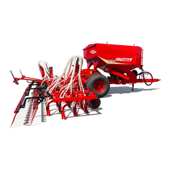
- Page 1 VESTA-2813 SM / NS PLUS Trailed pneumatic seed drill USER’S MANUAL COMMISSIONING, MAINTENANCE AND DOSAGE WWW.SOLAGRUPO.COM...
- Page 2 SOLÀ Seed Drills and Fertilizer Spreaders are manufactured in a factory specialised exclusively in this seg- ment and backed by the experience in use of many thousands of users. They are high-tech machines designed for long, trouble-free service in a wide variety of conditions, equipped with simple, effective devices for excellent performance with minimum maintenance.
-
Page 3: Table Of Contents
TABLE OF CONTENTS 1- INTRODUCTION ................................5 2. SAFETY INSTRUCTIONS ............................. 6 2.1 SAFETY SYMBOLS ..................................6 2.2 GENERAL SAFETY PROVISIONS ..............................7 2.3 LOADING AND UNLOADING INSTRUCTIONS .......................... 8 3. GENERAL DESCRIPTION .............................. 9 3.1 OVERVIEW OF THE MACHINE ..............................9 3.2 TECHNICAL SPECIFICATIONS .............................. - Page 4 7. DISTRIBUTION TYPE ..............................54 7.1 WITH MECHANICALLY DRIVEN TURBINE ..........................54 7.2 WITH HYDRAULICALLY DRIVEN TURBINE ..........................54 8. MAINTENANCE ................................. 55 8.1 FREQUENCY OF CHECKS ................................56 8.2 SCREW CONNECTIONS ................................57 8.3 CLEANING THE SEED DRILL ..............................57 8.4 GREASING AND LUBRICATION ..............................
-
Page 5: 1- Introduction
1- INTRODUCTION READ THE INSTRUCTIONS AND RECOMMENDATIONS in this The first chapters contain the Technical Characteristics, the manual before using THE VESTA-2813 SEED DRILL. This Safety Instructions and Basic Concepts for Sowing. The ba- will reduce the risk of accidents, prevent damage to the sic knowledge required to operate the machine is covered in seed drill due to improper use, increase its performance and the sections on Commissioning and Maintenance. -
Page 6: Safety Instructions
2. SAFETY INSTRUCTIONS 2.1 SAFETY SYMBOLS You will find three types of safety and hazard symbols in this manual: To make it easier to work To avoid damaging the To avoid personal injuries. with the seed drill. seed drill or the optional accessories. -
Page 7: General Safety Provisions
2.2 GENERAL SAFETY PROVISIONS - Check that working and traffic conditions are safe each time before starting the machine. - Do not place foreign objects in the hopper. - Check that no-one is in the machine's working area or nearby. - Depressurise the circuit and stop the tractor en- - Observe the traffic signs and regulations when gine before working on the hydraulic system. -
Page 8: Loading And Unloading Instructions
2.3 LOADING AND UNLOADING INSTRUCTIONS THESE OPERATIONS MUST BE PERFORMED BY Fig. 2.1 QUALIFIED, EXPERIENCED PERSONNEL. CAUTION: THE TRUCK MUST BE LOADED AND UNLOADED WITH THE ASSISTANCE OF A GANTRY CRANE, IF POSSIBLE. SEE SECTION 3.2 TECHNI- CAL CHARACTERISTICS FOR THE LOAD THAT THE GANTRY CRANE MUST BEAR. -
Page 9: General Description
3. GENERAL DESCRIPTION 3.1 OVERVIEW OF THE MACHINE Fig. 3.1 HOPPER: (depending on the model) 100% SEED STOPS and LATCHES DISTRIBUTION TRANSMISSION WHEEL 60/40% SEED/FERTILIZER COULTER UNIT FOLDING HEAD (depending on the model) 70/30% SEED/MICRO (inside) TRACK MARKERS (optional) WORK LAMPS TRANSPORT LIGHTS... -
Page 10: Machine Identification
3.3 MACHINE IDENTIFICATION 3.4 USE ACCORDING TO DESIGN The machine has an IDENTIFICATION PLATE on the carriage The VESTA-2813 seed drill has been specifically designed chassis, which specifies: for sowing cereals and other grain seeds and adding fertiliz- er (depending on the model). MAQUINARIA AGRÍCOLA SOLÀ... -
Page 11: Key Concepts For Sowing
4. KEY CONCEPTS FOR SOWING Very deep sowing: 8 to 10 cm 4.1 SOIL • Very slender stem. No till- A well-prepared soil significantly improves sowing quality. It Fig. 4.3 Fig. 4.3 ers and a single leaf. is not possible to obtain good results if the soil is in large •... -
Page 12: Commissioning
5. COMMISSIONING The points to be taken into account before using the ma- Fig. 5.1 chine are described below: • Make sure that the machine's mechanical components are well lubricated. Grease the mechanical components regu- larly (see section 8.4 GREASING AND LUBRICATION). •... -
Page 13: Electrical Connections
5.2 ELECTRICAL CONNECTIONS 5.2.3 ISOBUS The machine has electrical connections for: The machine must have the 9-pin connec- tor to connect to the tractor's ISOBUS (ac- • SIGNALLING LIGHTS and WORK LAMPS. cording to ISO 11783). • ISOBUS CONNECTION (depending on the model). 5.2.1 WORK LAMPS MAKE SURE THAT THE WORK LAMPS ARE TURNED OFF WHEN TRANSPORTING THE MA-... - Page 14 There is a hydraulic flow controller inside the carriage to en- Depending on the model, the machine is equipped with sure that the coulter unit is lowered smoothly to the ground safety latches (1, Fig. 5.5). These must be used to secure the (Fig.
-
Page 15: Transport Position
5.4 TRANSPORT POSITION 3- Lift the side units and make sure that the safety latches have been secured with the bolts (Fig. 5.9). With the machine coupled to the tractor and the hydraulic circuits connected to the tractor, follow the steps below to transport the machine: Fig. - Page 16 IMPORTANT: DEPENDING ON THE MACHINE Fig. 5.13 Fig. 5.13 MODEL, IF HYDRAULIC PRESSURE IS APPLIED AND THE TRANSMISSION WHEEL IS NOT LIFTED BUT THE COULTER UNIT AND THE TRACK ERAS- ER ARE, CHECK THAT THE SHUT-OFF VALVE AND THE THROTTLE LOCATED NEXT TO THE TRANSMISSION WHEEL ARE OPEN (FIG.
-
Page 17: Loading And Emptying The Hoppers
5.5 LOADING AND EMPTYING THE HOPPERS The braking system has a valve located at the front of the machine. This valve is regulated by means of a lever (Fig. 5.16), which will be placed in the correct position according It is best to use a continuous loader for safe, fast hopper to the hopper's filling level: loading. -
Page 18: Seed/Fertilizer Hopper (Depending On The Model)
5.5.1 SEED/FERTILIZER HOPPER 3- Release the tarpaulin locking device by pulling out the handle slightly and then turning it (Fig. 5.23). (depending on the model) 4- Take the crank handle and place it on the end of the tarpaulin (Fig. 5.24). Turn the handle to remove the tarpaulin (Fig. 5.25). To FILL the hopper, follow the steps below: Fig. - Page 19 To EMPTY the hopper, follow the steps below: 4- Open the dispensers provided with the machine (depend- ing on the model): 1- Place a sack or container under the product exits, then 4.A- Models with mechanical transmission: guide the emptying hoses (depending on the model) to 4.A.1- Empty the dispenser through the emptying the desired location.
- Page 20 4.B- Models with electric transmission: 4.B.1- Pull out the "R" pin (Fig. 5.35). 4.B.2- Unscrew the knobs (Fig. 5.36). 4.B.3- Pull out the side piece and remove the roller (Fig. the material accumulated in 5.37 and Fig. 38); the dispenser will then start to empty CLEAN THE DISPENSER WITH A BRUSH AND/OR COMPRESSED AIR.
- Page 21 5- Close the guillotine doors above the dispensers (Fig. 5.39). 6- Close the product exits and secure them with the knob (Fig. 5.40). Fig. 5.37 Fig. 5.37 Fig. 5.39 Fig. 5.39 Fig. 5.40 Fig. 5.38 Fig. 5.38 - 21 -...
-
Page 22: Support Legs
5.6 SUPPORT LEGS 5.6.1 FRONT SUPPORT LEG The front support leg is located on the hopper tow bar. To The machine is equipped with one support leg for the car- LOWER the support leg: riage (see section 5.6.1 FRONT SUPPORT LEG) and three or four support legs for the coulter unit, depending on the 1- Hold the support leg and release the latches so that the model (see section 5.6.2 REAR SUPPORT LEGS). -
Page 23: Rear Support Leg
5.6.2 REAR SUPPORT LEGS To RAISE the support leg: The rear support legs are located on the coulter unit. To IMPORTANT: WITH THE MACHINE COUPLED RAISE or LOWER the support leg: TO THE TRACTOR. 1- Remove the pin and the bolt (Fig. 5.45) to release the leg. 2- Move the support leg to the desired position (Fig. -
Page 24: Parking
5.7 PARKING 5.8 END OF WORK WITH THE MACHINE The transport wheels must be held by blocks when unhitch- • Empty the seed and fertilizer hopper completely: ing the seed drill from the tractor and parking it (Fig. 5.48). The blocks are located at the front of the machine (Fig. 5.49). •... -
Page 25: Adjustments
6. ADJUSTMENTS This chapter describes the adjustments to be made to the 6.2 DEPTH CONTROL VESTA-2813 seed drill in order to adapt it to the requirements of the soil and the type of seed to be sown. The values given The sowing depth is controlled by means of: in this manual may vary depending on ground conditions, climate factors or machine condition. - Page 26 5- Once the central section has been set. Lower the depth Fig. 6.3 Fig. 6.3 control wheels of the machine's folding parts until they touch the ground, proceeding as specified in section 6.2.2 DEPTH CONTROL WHEELS. Observe the depth of the machine's end coulters.
-
Page 27: Depth Adjusters
6.2.1 DEPTH ADJUSTERS The sowing depth will be defined by the main adjusters (3, Fig. 6.5). Both must be adjusted to the same depth. The ad- justers are located at the rear of the machine. Fig. 6.5 Fig. 6.7 Fig. 6.7 FOR QUICK ADJUSTMENT OF THE SOWING DEPTH, SET THE ADJUSTERS (3, FIG. -
Page 28: Depth Control Wheels
6.2.2 DEPTH CONTROL WHEELS 4- Put the specific wrench back in its place and lock the wheel with the locking handle (Fig. 6.12). The coulter unit's side wheels (4, Fig. 6.9) control the folding parts' sowing depth. Use the specific wrench supplied with the machine to adjust these wheels. -
Page 29: Folding Part Angle Stops
6.2.4 COULTERS 6.2.3 FOLDING PART ANGLE STOPS The seed drill is fitted with coulters for opening furrows in There are adjustable stops at the point where the folding which the seeds or fertilizer will be placed. Several coulter parts rest on the chassis that can be used to change the drop models are available for different soil conditions: angle (Fig. -
Page 30: Sm Model
6.2.4.1 SM MODEL HEIGHT-ADJUSTABLE COULTERS These coulters are aligned with the wheels of the tractor and This model is fitted with two types of coulter: seed drill. FIXED COULTERS IMPORTANT: IT IS ADVISABLE TO ADJUST These coulters are not height-adjustable. Consequently, the THESE COULTERS IF THE RUTS ARE VERY DEEP. -
Page 31: Ns Plus Model (Straight Coulters)
6.2.4.2 NS PLUS MODEL (STRAIGHT COULTERS) 6.2.4.3 NS PLUS MODEL (SUFFOLK COULTERS) This model is fitted with two types of coulter: These coulters are not height-adjustable. Consequently, the sowing depth will be defined by the adjusters on the coulter FIXED COULTERS unit's chassis (see section 6.2.1 DEPTH ADJUSTERS). -
Page 32: Dosage
6.3 DOSAGE 6.3.1 VOLUMETRIC DISPENSER This seed or fertilizer dispenser (Fig. 6.22 and Fig. 6.23) pro- Depending on the machine model, different types of dis- vides 2 dosage modes: penser can be installed. The available types are the following: - For NORMAL-sized seeds or fertilizers (Position N). - For SMALL/FINE seeds or fertilizers, with minimum flows •... -
Page 33: Regular Seed Or Conventional Fertilizer
6.3.1.1 REGULAR SEED OR CONVENTIONAL FERTILIZER Proceed as follows for sowing with REGULAR SEEDS or fer- tilising with CONVENTIONAL FERTILIZERS: 1- The locking ring must be in position N (Fig. 6.29). IMPORTANT: IF IT IS NECESSARY TO CHANGE FROM POSITION F TO POSITION N, PROCEED AS DESCRIBED IN SECTION 6.3.1 VOLUMETRIC DIS- PENSER. -
Page 34: Fine Seed Or Microgranulate Fertilizer
6.3.1.2 FINE SEED OR MICROGRANULATE 3- Set the dispenser sprockets to position F, (Fig. 6.31). 4- For models equipped with a NEUMASEM MFDC monitor, FERTILIZER the controller must be set to MICRO mode (see the moni- tor's specific manual). Proceed as follows for sowing with FINE SEEDS or fertilising with MICROGRANULATE FERTILIZERS: Fig. -
Page 35: Roller Dispenser
6.3.2 ROLLER DISPENSER This dispenser has a roller that can be assembled with differ- ent numbers of sectors (e.g. 4 sectors, Fig. 6.32). Between 1 and 7 sectors can be mounted. Fig. 6.34 Fig. 6.34 Fig. 6.32 THERE ARE SEVERAL TYPES OF SECTORS FOR: HIGH, MEDIUM, LOW OR VERY LOW DOSES (FIG. -
Page 36: Dispensers For Fertilizer And/Or Microgranulator Kits
6.3.3 DISPENSERS FOR FERTILIZER AND/ WHEN TAKING OUT THE ROLLER, TAKE CARE NOT TO LOSE THE O-RINGS ON THE SHAFT OR MICROGRANULATOR KITS (SMALL) AND ON THE SIDE PIECE (LARGE) AND REPOSITION THEM CORRECTLY WHEN ASSEM- There are several fertilizer and/or microgranulator kits. BLING THE ROLLER (FIG. -
Page 37: Internal Kit Hopper - Fertilizer And/Or Microgranulate Dispenser
6.3.3.1 INTERNAL KIT HOPPER - FERTILIZER FOR MODELS WITH MECHANICAL TRANSMIS- SION AND A SINGLE DISTRIBUTION HEAD, IF AND/OR MICROGRANULATE DISPENSER THE DOSE TO BE DISTRIBUTED IS LESS THAN THAT SPECIFIED IN THE DOSAGE TABLES, ONE This kit for conventional or microgranulate fertilizer has two DISPENSER SHOULD BE OVERRIDDEN. -
Page 38: External Kit Hopper - Microgranulate Fertilizer Dispenser
6.3.3.2 EXTERNAL KIT HOPPER - MICRO- Release the two fasteners to remove the chain cover (Fig. 6.45). GRANULATE FERTILIZER DISPENSER This kit for microgranulate fertilizer has two hoppers (Fig. 6.44) with a total capacity of 410 litres; each hopper feeds a dispenser. - Page 39 Remove the ring pins and change the sprockets as required by Fig. 6.49 Fig. 6.49 the dose it is wished to distribute. Once modified, reassemble the ring pins (Fig. 6.47). VERY IMPORTANT: TO MODIFY THE TRANS- MISSION, SEE THE DOSAGE TABLES IN SEC- TION 9.3.3 EXTERNAL KIT HOPPER WITH ME- CHANICAL TRANSMISSION.
-
Page 40: Setting The Seed Dose
6.4 SETTING THE SEED DOSE The following describes a practical method for calculating the kilograms per hectare to be distributed, based on the number of plants per square metre that we want to obtain. Using high-quality certified seeds is not enough to deter- mine the weight in kilograms to be distributed with the ma- chine, since the final result of the harvest will depend on the number of plants that reach full maturity. -
Page 41: Flow Pre-Test
6.5 FLOW PRE-TEST 6.5.1 MODELS WITH MECHANICAL TRANS- MISSION Having determined the seed dose to be distributed (see sec- tion 6.4 SETTING THE SEED DOSE), and before starting work, A series of steps must be taken before performing the test: a flow test should be carried out to confirm that the dose to 1- Couple the machine to the tractor in a slightly raised posi- be distributed is the desired dose. - Page 42 7- Next, place the hand crank in the transmission wheel (Fig. FOR MODELS WITH A DUAL SEED (OR SEED AND FERTILIZER) DISPENSER, THE CALIBRA- 6.56). Turn the wheel anticlockwise the number of turns TION TEST MUST BE PERFORMED IN BOTH DIS- indicated in the table below (the number of turns will vary PENSERS AT THE SAME TIME.
- Page 43 9- Turn the seed drill transmission wheel the number of UPON COMPLETING THE FLOW TESTS, CLOSE turns given in the table in point 7 of this section. THE VENTURI INJECTOR COVER, MOVE THE CALIBRATION CONTROL TO THE "OK" POSI- AFTER TURNING THE WHEELS THE REQUIRED TION AND LOCK IT (Fig.
-
Page 44: Models With Isobus Electric Transmission
6.5.2 MODELS WITH ISOBUS ELECTRIC TRANS- 5- Place the bag supplied or a container under the Venturi injector outlet (Fig. 6.62) MISSION A series of steps must be taken before performing the test: 1- Couple the machine to the tractor in a slightly raised posi- Fig. - Page 45 IF THE MACHINE HAS THE INTERNAL CONVEN- A VALUE MUST BE ENTERED FOR THE CALIBRATION TIONAL OR MICROGRANULATE FERTILIZER KIT, FACTOR. IF THE FACTOR IS NOT CORRECT, IT WILL BOTH PIPES OF THE MICROGRANULATE AND/ NOT BE POSSIBLE TO PERFORM THE CALIBRATION. OR FERTILIZER KIT MUST BE DISCONNECTED FROM THE COLLECTION BOXES IN ORDER TO 9- After entering the 3 desired values, check the minimum...
- Page 46 10- With the controller settings made. Hold down the cali- UPON COMPLETING THE FLOW TESTS, CLOSE bration button (Fig. 6.68) to start the calibration test. THE VENTURI INJECTOR COVER, MOVE THE CALIBRATION CONTROL TO THE "OK" POSI- TION AND LOCK IT (Fig. 6.70). HOLD DOWN THE BUTTON TO COLLECT THE MAXIMUM QUANTITY OF PRODUCT.
-
Page 47: Field Test For Dosage (Models With Mechanical Transmission)
6.6 FIELD TEST FOR DOSAGE (models with 2- Make a mark on the tyre to make it easier to count wheel turns while moving (Fig. 6.72). mechanical transmission) The field test to verify the dose that the machine will dis- Fig. -
Page 48: Mechanical Transmission
6.7 MECHANICAL TRANSMISSION The transmission can be varied through the transmission box to adjust the dose that the machine will distribute (Fig. 6.73). FOR MODELS PRIOR TO 2018, THE TRANSMIS- SION CANNOT BE MODIFIED AND THE TRANS- MISSION IS CONSIDERED TO BE IN POSITION R. Fig. -
Page 49: Harrow
6.8 HARROW VERY IMPORTANT: THE CHAIN MUST BE PROPERLY ALIGNED. OTHERWISE, IT MAY STOP DRIVING. The harrow has several adjustments to adapt to different types of soils. It can be adjusted by: HEIGHT. THE DOSAGE TABLES REFER TO THE POSITION Adjust the bottom nut (1, Fig. -
Page 50: Compacting Roller
6.9 COMPACTING ROLLER When the roller is raised to disconnect it, the harrow must be moved back following these steps: 1- Loosen the nut (Fig. 6.83). There are two BOLTS on each coulter that allow the following adjustments: a. Use the top bolt (1, Fig. 6.81) to lock the roller's position. b. -
Page 51: Track Erasers
6.10 TRACK ERASERS To override the track eraser, proceed as follows: 1- Raise the coulter unit to its maximum height (Fig. 6.88). The seed drill is equipped with height-adjustable track eras- er arms to clear the tractor's tracks. To change the working depth, loosen the retaining bolts (Fig. -
Page 52: Hydraulic Track Markers
6.11 HYDRAULIC TRACK MARKERS To calculate the horizontal distance BETWEEN THE TRACK MARKER DISC AND THE OUTERMOST COULTER (B, Fig. 6.91), apply the following formula: The track marker arms are adjustable by: - LENGTH, horizontal distance between the disc and the Fig. - Page 53 To set the track marker disc's distance and inclination, pro- ADJUST THE WORKING LENGTH TO THE DIS- ceed as follows: TANCE B CALCULATED PREVIOUSLY. (B= DIS- TANCE BETWEEN THE TRACK MARKER DISC 1- Adjust the length of the first section of the track marker by AND THE LAST COULTER CLOSEST TO THE loosening the 2 nuts and bolts (1, Fig.
-
Page 54: Distribution Type
7. DISTRIBUTION TYPE IMPORTANT: MAKE SURE TO ROTATE THE CONNECTION TURBINE AT THE RATED SPEED BEFORE THE Connect the quick-connect fitting of the small turbine hose TRANSMISSION WHEEL STARTS TO TURN. WHEN to a pressure outlet on the tractor. Connect the 1/2" hose SOWING HAS FINISHED, DO NOT LOWER THE with the large quick-connect fitting to a free return. -
Page 55: Maintenance
8. MAINTENANCE IN CASE OF BREAKDOWN, STOP THE MA- Before performing any task on the machine, the following CHINE IMMEDIATELY AND REMOVE THE KEY factors must be taken into account: FROM THE IGNITION. GET DOWN FROM THE TRACTOR AND VISUALLY CHECK THE EXTENT - Machine maintenance and repair operations must be car- OF THE PROBLEM. -
Page 56: Frequency Of Checks
8.1 FREQUENCY OF CHECKS KEEP THE COULTER UNITS CLEAN; ACCUMULA- TION OF SOIL, STONES, GRASS, ETC. MAY OB- STRUCT THE SEEDING LINES. The frequencies of maintenance operations are given as a guideline and may vary depending on the type of service and use of the machine, environment, temperature, climate factors, etc. -
Page 57: Screw Connections
8.2 SCREW CONNECTIONS 8.3 CLEANING THE SEED DRILL All of the seed drill's screw connections should be checked Clean the seed drill with pressurized air; do not wash with and, if necessary, retightened. water under any circumstances. ALL NUTS AND BOLTS SHOULD BE CHECKED Foreign objects may get stuck in certain parts of the machine AND TIGHTENED AFTER THE FIRST 10 HOURS during operation. -
Page 58: Greasing And Lubrication
8.4 GREASING AND LUBRICATION 8.5 TYRE PRESSURE All metal components of the machine that are not painted Check the air pressure in the tyres before using the seed drill. are exposed to atmospheric and climate factors, which may cause rusting. Consequently, it is important to grease and In general and in poorly prepared soils, it is recommended lubricate these parts properly. -
Page 59: Dosage Tables
9. DOSAGE TABLES FOR PRECISION WORK, FOLLOW THE DOSAGE THE QUANTITIES INDICATED IN THE TABLES PROCEDURE DESCRIBED IN SECTION 6 OF THIS SHOULD BE CONSIDERED APPROXIMATE ESTI- MANUAL. MATES, SINCE THE EXPECTED FLOW RATE MAY VARY DUE TO THE POSSIBLE PRESENCE OF DIS- INFECTANT POWDER, VARIABLE SEED SIZE, FER- TILIZER GRANULOMETRY, DENSITY, SPECIFIC GRAVITY, MOISTURE CONTENT, ETC. -
Page 60: Regular Seed Or Conventional Fertilizer
9.1.1 REGULAR SEED OR CONVENTIONAL FERTILIZER DISPENSER NORMAL POSITION (kg/ha) WORKING WIDTH (cm) NUMBER OF DISPENSERS GEARBOX SPEC. GRAVITY (kg/L) 16.4 24.5 12.3 16.4 20.4 24.5 16.4 24.5 24.5 12.3 18.4 24.5 24.5 16.4 24.5 20.4 24.7 28.8 WHEN THE DOSE TO BE SOWN (kg/ha) IS VERY SMALL (GRADER POSITION <= 10), A MORE UNIFORM SEEDING CAN BE OBTAINED BY MICRODOSAGE, EVEN IN THE NORMAL SOWING RANGE (CEREAL AND THICK SEEDS). - Page 61 DISPENSER NORMAL POSITION (kg/ha) WORKING WIDTH (cm) NUMBER OF DISPENSERS GEARBOX SPEC. GRAVITY (kg/L) 14.4 21.6 28.9 10.8 14.4 18.0 21.6 28.9 14.4 21.6 28.9 21.6 10.8 16.2 21.6 27.1 21.6 28.9 14.4 21.6 28.9 28.9 18.0 27.1 21.8 25.4 29.0 WHEN THE DOSE TO BE SOWN (kg/ha) IS VERY SMALL (GRADER POSITION <= 10), A MORE UNIFORM SEEDING CAN BE OBTAINED BY MICRODOSAGE, EVEN IN THE NORMAL SOWING RANGE (CEREAL AND THICK SEEDS).
- Page 62 DISPENSER NORMAL POSITION (kg/ha) WORKING WIDTH (cm) NUMBER OF DISPENSERS GEARBOX SPEC. GRAVITY (kg/L) 14.0 21.0 28.0 10.5 14.0 17.5 21.0 28.0 14.0 21.0 28.0 21.0 10.5 15.8 21.0 26.3 21.0 28.0 14.0 21.0 28.0 28.0 17.5 26.3 21.1 24.7 28.2 WHEN THE DOSE TO BE SOWN (kg/ha) IS VERY SMALL (GRADER POSITION <= 10), A MORE UNIFORM SEEDING CAN BE OBTAINED BY MICRODOSAGE, EVEN IN THE NORMAL SOWING RANGE (CEREAL AND THICK SEEDS).
- Page 63 DISPENSER NORMAL POSITION (kg/ha) WORKING WIDTH (cm) NUMBER OF DISPENSERS GEARBOX SPEC. GRAVITY (kg/L) 12.7 19.1 25.5 12.7 15.9 19.1 25.5 12.7 19.1 25.5 19.1 28.7 14.3 19.1 23.9 28.7 19.1 28.7 25.5 12.7 19.1 25.5 25.5 15.9 23.9 19.2 28.8 22.4 25.6...
-
Page 64: Fine Seed Or Microgranulate Fertilizer
9.1.2 FINE SEED OR MICROGRANULATE FERTILIZER - 64 -... - Page 65 - 65 -...
- Page 66 - 66 -...
- Page 67 - 67 -...
-
Page 68: Roller Dispenser Calibration Factor Table
9.2 ROLLER DISPENSER CALIBRATION FACTOR TABLE NUMBER OF SECTORS SPECIFIC GRAVITY (kg/L) 103 129 154 154 193 360 450 540 245 294 - 68 -... -
Page 69: Tables For Conventional And Microgranulate Fertilizer Kits
9.3 TABLES FOR CONVENTIONAL OR MICROGRANULATE FERTILIZER KITS CONVENTIONAL CONVENTIONAL MICRO FERTILIZER MICRO FERTILIZER FERTILIZER FERTILIZER 9.3.1 INTERNAL KIT HOPPER WITH MECHANICAL TRANSMISSION The table below shows the values that both dispensers will The table below shows the values that both dispensers will distribute with the sectors for MICROGRANULATE FERTILIZER: distribute with the sectors for CONVENTIONAL FERTILIZER: MICRO FERTILIZER DISPENSERS (kg/ha) -
Page 70: External Kit Hopper With Mechanical Transmission
9.3.3 EXTERNAL KIT HOPPER WITH MECHANICAL TRANSMISSION VERY IMPORTANT: THE TABLES IMPORTANT: IF THE COULTER UNIT HAS TWO DISTRIBUTION BELOW SHOW THE VALUES THAT HEADS, ONLY ONE PRODUCT CAN BE DISPENSED. IN THIS WILL BE DISTRIBUTED BY A SINGLE CASE, BOTH TRANSMISSIONS MUST HAVE THE SAME SET- DISPENSER. - Page 71 STANDARD ROLLER STANDARD ROLLER MICROGRANULATE FERTILIZER DOSAGE WITH 1 STANDARD ROLLER (kg/ha) WIDTH 12.02 16.90 14.79 10.61 14.92 13.05 10.30 14.49 12.68 9.37 13.17 11.53 12.06 16.96 14.84 10.64 14.96 13.09 10.34 14.53 12.72 9.40 13.21 11.56 12.34 17.35 15.18 10.89 15.31 13.40...
- Page 72 HALF-DOSE ROLLER HALF-DOSE ROLLER MICROGRANULATE FERTILIZER DOSAGE WITH 1 HALF-DOSE ROLLER (kg/ha) WIDTH 2.97 4.18 3.66 2.62 3.69 3.23 2.55 3.58 3.13 2.31 3.26 2.85 3.22 4.53 3.96 2.84 3.99 3.49 2.76 3.88 3.39 2.51 3.53 3.09 3.25 4.58 4.00 2.87 4.04 3.53...
- Page 73 HALF-DOSE ROLLER HALF-DOSE ROLLER MICROGRANULATE FERTILIZER DOSAGE WITH 1 HALF-DOSE ROLLER (kg/ha) WIDTH 6.01 8.45 7.40 5.30 7.46 6.53 5.15 7.24 6.34 4.68 6.59 5.76 6.03 8.48 7.42 5.32 7.48 6.55 5.17 7.27 6.36 4.70 6.61 5.78 6.17 8.67 7.59 5.44 7.65 6.70...
-
Page 74: External Kit Hopper With Isobus
9.3.4 EXTERNAL KIT HOPPER WITH ISOBUS IMPORTANT: THE TABLE BELOW SHOWS IMPORTANT: IF THE COULTER UNIT HAS TWO THE CALIBRATION FACTOR TO BE ENTERED IN DISTRIBUTION HEADS, ONLY ONE PRODUCT THE MONITOR DEPENDING ON THE ROLLER CAN BE DISPENSED. IN THIS CASE, THE SAME MOUNTED. - Page 75 - 75 -...
- Page 76 - 76 -...
- Page 77 NOTES DATE NOTES - 77 -...
- Page 78 DATE NOTES - 78 -...
- Page 80 MAQUINARIA AGRÍCOLA SOLÀ, S.L. Ctra. de Igualada, s/n. 08280 CALAF (Barcelona) Spain Tel.(+34) 93 868 00 60 - Fax (+34) 93 868 00 55 WWW.SOLAGRUPO.COM...
Need help?
Do you have a question about the VESTA-2813 SM and is the answer not in the manual?
Questions and answers