
Related Manuals for Sola A-6000 SM


Summary of Contents for Sola A-6000 SM
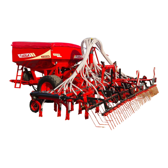
- Page 1 A-6000 SM / NS PLUS Trailed pneumatic seed drill STARTING MANUAL MAINTENANCE AND DOSAGE W W W. S O L A G R U P O. C O M...
- Page 2 SOLÁ seed drillers and fertilizer spreaders are manufactured in a highly specialized environment and our factory has a vast customer-endorsed experience. SOLÁ machines use highly advanced technology and are guaranteed to work without malfunctions in a great variety of conditions. They are provided with easy-to-use and efficient devices. SOLÁ...
-
Page 3: Table Of Contents
TABLE OF CONTENTS 1. INTRODUCTION ................................5 2. SAFETY INSTRUCTIONS ............................. 6 2.1 SAFETY SYMBOLS ..................................6 2.2 GENERAL SAFETY INSTRUCTIONS ............................7 2.3 LOADING AND UNLOADING INSTRUCTIONS ......................... 8 3. GENERAL DESCRIPTION ............................. 9 3.1 OVERVIEW OF THE MACHINE ..............................9 3.2 TECHNICAL SPECIFICATIONS .............................. - Page 4 7. DISTRIBUTION TYPE ..............................42 7.1 WITH MECHANICAL DRIVE TURBINE ............................42 7.2 WITH HYDRAULIC DRIVE TURBINE ............................43 8. SOWING ELECTRONIC CONTROL ..........................44 8.1 CONTROL PANEL, DESCRIPTION ............................. 44 8.2 RUNNING SPEED -C1 ................................. 45 8.3 TOTAL AREA / SEED DRILLER WIDTH - C2 ..........................45 8.4 CONTROL PANEL WITH TRACK MARKER (OPTIONAL) ......................
-
Page 5: Introduction
1. INTRODUCTION It is essential to READ AND FOLLOW THE INSTRUCTIONS In the first chapters you will find the Technical Characteris- AND RECOMMENDATIONS in this manual before operating tics and Safety Instructions, as well as some essential sowing the SEED DRILLER A-6000. Careful reading enables maxi- concepts. -
Page 6: Safety Instructions
2. SAFETY INSTRUCTIONS 2.1 SAFETY SYMBOLS In this operating manual you will find three different symbols relating to safety: To facilitate operation with the seed drill. To avoid damages on the seed drill or in the optional equipments. This symbol warns of the risk of injury. On the machine, you will find the following symbols: Danger of infection from escaping hydraulic Read the instructions carefully and observe the... -
Page 7: General Safety Instructions
2.2 GENERAL SAFETY INSTRUCTIONS - Before starting the machine, please check the - Never leave the tractor’s driver’s seat while the machine is in good condition for work and is machine is in operation. safe for road use. - Do not deposit external elements inside the - Check that visibility is clear around the ma- hopper. -
Page 8: Loading And Unloading Instructions
2.3 LOADING AND UNLOADING INSTRUCTIONS THESE OPERATIONS SHOULD BE PERFORMED WARNING: SEE SECTION 3.2, TECHNICAL ONLY BY QUALIFIED AND EXPERIENCED PER- CHARACTERISTICS, FOR KNOWING THE LOAD SONNEL. THAT THE BRIDGE CRANE SHALL SUPPORT LOADING AND UNLOADING THE MACHINE MUST BE PERFORMED, IF POSSIBLE, USING A BRIDGE The images show the towrope arrangements and mooring CRANE. -
Page 9: General Description
3. GENERAL DESCRIPTION 3.1 OVERVIEW OF THE MACHINE Fig. 3.1 ENTRY TRACK MARKERS DISTRIBUTION LADDER HEAD DEPTH CONTROL HOPPER WHEEL LEVEL TENSIONER TURBINE HARROW TRANSMISSION WHEEL TRACK ERASER FRONT FLOATING COMPACTING COULTERS SUPPORT FOOT WHEEL ROLLER 3.2 TECHNICAL SPECIFICATIONS MACHINE TYPE DISTANCE BETWEEN HOPPER CAPACITY ESTIMATED... -
Page 10: Identification Of The Machine
3.3 IDENTIFICATION OF THE MACHINE 3.4 USAGE ACCORDING TO DESIGN All the machines have an IDENTIFICATION PLATE on the The A-6000 seed driller has been designed for sowing of ce- frame, specifying: reals and other kind of grain seeds. The machine has been designed for being dragged by an MAQUINARIA AGRÍCOLA SOLÀ... -
Page 11: Fundamental Concepts For Planting
4. FUNDAMENTAL CONCEPTS FOR PLANTING Too deep sowing: from 8 to 10 cm 4.1 TERRAIN • Very thin stem. Not tiller- The better terrain conditions, the better the sowing quali- Fig. 4.3 Fig. 4.3 ing and one leaf. ty. A good labour cannot be carried out in big clods or very •... -
Page 12: Commissioning
5. COMMISSIONING 5.1 COUPLING THE SEED DRILLER TO THE TRACTOR The issues to take into account before starting the machine are detailed below: The A-6000 seed driller is fitted with a rotating shaft-ring hook. • Verify that the mechanical components are well greased. Periodically grease the mechanical components (see sec- tion 9.4 LUBRICATION AND GREASING POINTS). - Page 13 2- Plug in the electrical connector for the lightning The machine has electrical connections for: equipment. 3- Place the front support feet in vertical position (see sec- • SIGNALLING LIGHTS and WORK LAMPS. tion 5.6 SUPPORT FEET). • CONNECTION TO ISOBUS (depending on the model). 4- Lower the central sowing equipment until touching the ground.
-
Page 14: Coupling And Adapting The Pto Shaft
5.2 COUPLING AND ADAPTING THE PTO 3- Cut the plastic and metal surplus parts with the same size and reassembly the transmission (Fig. 5.4). SHAFT Once the seed driller is coupled to the tractor, the TRANS- MISSION MUST BE ADAPTED for the equipment with me- chanical turbine. -
Page 15: Hydraulic System
5.3 HYDRAULIC SYSTEM For machine versions with track eraser, this element can be excluded with the stopcock (Fig. 5.7) placed between the hopper and the seed drill. See the stopcock positions in the The machine requires hydraulic connexion for: images, being: OPEN: for including the track eraser, and CLOSED: for excluding the track eraser. -
Page 16: Transportation Position
5.4 TRANSPORTATION POSITION ACCORDING WITH THE WORKING CONDITIONS DEFINED BY THE FINAL USER AND THE OPTIONS INCORPORATED, THE MACHINES COULD NOT With the machine coupled with the tractor and the hydraulic MEET THE REQUIREMENTS STABLISHED BY THE circuits connected to the tractor distributor, follow the steps LAW TO TRANSPORT THEM ON PUBLIC ROADS. -
Page 17: Loading And Unloading The Hopper
5.5 LOADING AND UNLOADING THE 5- Take the handle at the ladder side (Fig. 5.17) and place it at the end of the canvas (Fig. 5.18). Turn the handle for re- HOPPER moving the canvas (Fig. 5.19). For a safe and fast hopper load, the best option is using a Fig. -
Page 18: Support Feet
5.6 SUPPORT FEET For fast HOPPER EMPTYING: 1- Loosen the wing nut (2, Fig. 5.21). The machine is fitted with a hopper support foot (see sec- tion 5.6.1 FRONT SUPPORT FEET) and two feet for the sowing equipment (see section 5.6.2 REAR SUPPORT FEET). Fig. -
Page 19: Front Support Foot
5.6.1 FRONT SUPPORT FOOT 5.6.2 REAR SUPPORT FOOT The rear support feet are locat- The front support foot is located at the hopper tow-bar. For ed in the sowing equipment. LOWERING the support foot: For LIFTING or LOWERING the support foot: 1- Remove the security pin (A, Fig. -
Page 20: Parking Brake
5.7 PARKING BRAKE 5.8 END OF MACHINE WORK Turn the lever to the right for activating the parking brake • Fully empty the hopper of any seed and fertilizer: and, turn it to the left for releasing. • Wash the machine with compressed air, particularly the containers used for chemical products (see section 9.2 SEED DRILLER CLEANING). -
Page 21: Adjustments
6. ADJUSTMENTS 6.1.1 TOW-BAR AND TRACTOR LEVELLING FOR COUPLING THE SEED DRILLER TO THE This chapter contains the necessary modifications necessary TRACTOR, PLACE THE TOWING HOOK POINT to adjust the A-6000 according to the terrain and seed. The AT THE LOWEST POSSIBLE POSITION; THERE- values herein provided may vary according to the terrain FORE, PLACE THE BOLT AND THE SECURITY PIN conditions, climate factors and the machine conditions. -
Page 22: Sowing Equipment Levelling
6.2 DEPTH CONTROLS 6.1.2 SOWING EQUIPMENT LEVELLING Level the sowing equipment by modifying the tensor (4. Fig. The sowing depth is controlled by means of: 6.3) placed in the rear part of the seed hopper. - DEPTH TINES see section 6.2.1. - DEPTH CONTROL WHEEL see section 6.2.2. -
Page 23: Depth Control Wheels
6.2.2 DEPTH CONTROL WHEELS 6.2.3 COULTERS The lateral wheels of the sowing equipment ((1, Fig. 6.6) con- The seed drill is fitted with coulters for opening furrows in trol the sowing depth at the foldable parts. For regulating which the seeds or fertilizer will be placed. Several coulter these wheels, use the wrench (2, Fig. -
Page 24: Sm Model
6.2.3.1 SM MODEL HEIGHT-ADJUSTABLE COULTERS These coulters are aligned with the wheels of the tractor and This model is fitted with two types of coulter: seed drill. FIXED COULTERS IMPORTANT: IT IS ADVISABLE TO ADJUST THE- These coulters are not height adjustable. Consequently, the SE COULTERS IF THE RUTS ARE VERY DEEP. -
Page 25: Ns-Plus Model
6.2.3.2 NS-PLUS MODEL 6.3 DOSAGE This model is fitted with two types of coulter: Depending on the machine model, different types of dispen- ser can be installed. The available types are the following: FIXED COULTERS • Volumetric. These coulters are not height •... -
Page 26: Volumetric Dispenser
6.3.1 VOLUMETRIC DISPENSER 6.3.1.1 NORMAL SEEDS (N position) Follow the following steps for sowing with NORMAL SEEDS: The seed dispenser (Fig. 6.14) allows two dosage modes: - NORMAL size seeds (N position). Fig. 6.16 - SMALL/FINE seeds, with minimum flows (F posi- tion). -
Page 27: Small Seeds (F Position)
6.3.1.2 SMALL SEEDS (F position) THE MICRO-DOSAGE SYSTEM ALLOWS BETTER DISTRIBUTING SMALL AND NORMAL SIZED SEEDS IN REDUCED AMOUNTS. Follow the steps below for sowing with SMALL SEEDS: Fig. 6.19 READ THE ADVISABLE VALUE FOR SMALL SEEDS WITH THE F MICRO-DOSAGE SYSTEM IN THE DOSAGE CHARTS (SEE SECTION 10). -
Page 28: Roller Dispenser
6.3.2 ROLLER DISPENSER This dispensers has a roller that can be set in sectors (e.g. 4 sectors, Fig. 6.23). Between 1 and 7 sectors can be mounted. Fig. 6.25 Fig. 6.25 Fig. 6.23 THERE ARE SEVERAL TYPES OF SECTORS FOR: HIGH, MEDIUM, LOW OR VERY LOW DOSES (Fig. -
Page 29: Dispensers For Fertilizer And/Or Microgranulate Kits
6.3.3 DISPENSERS FOR FERTILIZER AND/OR MI- WHEN TAKING OUT THE ROLLER, TAKE CARE NOT TO LOSE THE O-RING ON THE SHAFT (SMA- CROGRANULATE KITS LL) AND ON THE SIDE PIECE (LARGE) AND REPO- SITION THEM CORRECTLY WHEN ASSEMBLING There are several fertilizer and/or microgranulate kits. Na- THE ROLLER (Fig. -
Page 30: Internal Kit Hopper - Fertilizer And/Or Microgranulate Dispenser
6.3.3.1 INTERNAL KIT HOPPER - FERTILIZER AND/ FOR MODELS WITH MECHANICAL TRANSMIS- SION AND A SINGLE DISTRIBUTION HEAD, IF OR MICROGRANULATE DISPENSER THE DOSE TO BE DISTRIBUTED IS LESS THAN THAT SPECIFIED IN THE DOSAGE TABLES, ONE This kit for conventional or microgranulate fertilizer has two DISPENSER SHOULD BE OVERRIDDEN. -
Page 31: Seed Dosage Adjustment
PLEASE NOTE THAT, IN SPRING, TILLERING IS ALWAYS LOWER AND, THEREFORE, THE SEED AMOUNT TO BE SOWN SHALL INCREASE. MAQUINARIA AGRÍCOLA SOLA, S.L., RECOM- MENDS THE FARMER TO SEEK PROFESSIONAL ADVICE ABOUT THIS SUBJECT, SUCH AS ITG DEL CEREAL, AGRICULTURAL UNION TRADES, ETC. -
Page 32: Seed Flow Pre-Testing
6.5 SEED FLOW PRE-TESTING 6.5.1 MODELS WITH MECHANICAL TRANSMISSION A series of previous steps must be performed for carrying Once the seed dosage is adjusted (see section 6.4 SEED DO- out the test: SAGE ADJUSTMENT), a flow test must be carried out to verify that the dose to be sowed is the same as the one indicated 1- Couple the machine to the tractor in a slightly raised posi- in the dosage charts. - Page 33 AFTER TURNING THE WHEELS, TURN ON THE TURBINE FOR A FEW SECONDS TO COLLECT THE PRODUCT REMAINING IN THE PRODUCT TRANSPORT PIPES. 10- After turning the wheel the required number of times, collect the microgranulate fertilizer. Subsequently, re- connect the transmission for the seed dispensers. 11- Accurately weigh the collected products.
-
Page 34: Models With Isobus Electrical Transmission
6.5.2 MODELS WITH ISOBUS ELECTRICAL TRANS- IMPORTANT: IN DOSAGES THAT ARE CLOSE TO TOTAL PRODUCT QUANTITIES OF 450 Kg/Ha MISSION (TAKE INTO ACCOUNT SEED, FERTILIZER AND MICROGRANULATE), CHECK THAT THERE IS A series of steps must be taken before performing the test: NO MATERIAL BUILDUP CLOGGING THE COM- 1- Couple the machine to the tractor in a slightly raised posi- PRESSED AIR SYSTEM. - Page 35 5- Place the supplied bag or a container underneath the IF THE MACHINE HAS THE INTERNAL CONVEN- Venturi injector exit (Fig. 6.43). TIONAL OR MICROGRANULATE FERTILIZER KIT, BOTH PIPES OF THE MICROGRANULATE AND/ OR FERTILIZER KIT MUST BE DISCONNECTED FROM THE COLLECTION BOXES IN ORDER TO Fig.
- Page 36 10- With the controller settings made. Hold down the cali- A VALUE MUST BE ENTERED FOR THE CALIBRA- TION FACTOR. IF THE FACTOR IS NOT CORRECT, bration button (Fig. 6.49) to start the calibration test. IT WILL NOT BE POSSIBLE TO PERFORM THE CA- LIBRATION.
-
Page 37: Seed Dose Field Testing
6.6 SEED DOSE FIELD TESTING CALIBRATION TEST. 1. Start In case of differences between the test and the dose being actually distributed by the machine due to, for instance, very Dispenser uneven or soft terrain or low-pressured wheel, etc., an ex- Operating speed perimental test can be performed to determine the ACTUAL AMOUNT OF ROTATIONS in the TRANSMISSION WHEEL. -
Page 38: Harrow
6.7 HARROW 6.8 TRACK ERASERS (OPTIONAL) The seed driller is fitted with track eraser coulters that can The harrow has several settings according to the type of ter- be adjusted in height for erasing the tractor marks. The rain. The settings that can be adjusted are: track markers can be eliminated. -
Page 39: Compacting Roller
6.9 COMPACTING ROLLER When the roller is raised to disconnect it, the harrow must be moved back following these steps: 1- Loosen the nut (Fig. 6.59). There are two BOLTS on each coulter that allow us to per- form the following adjustments: a. -
Page 40: Hydraulic Track Markers
6.10 HYDRAULIC TRACK MARKERS 6.10.1 TRACK MARKER LENGTH ADJUSTMENT For calculating the horizontal distance BETWEEN THE TRACK Track marker coulters are adjustable in: MARKER DISC AND THE OUTER COULTER (B, Fig. 57), follow - LENGTH, horizontal distance between the disc and the the following formula: outer element. -
Page 41: Track Marker Disc Inclination Adjustment
6.11 INCLINATION OF FOLDING PARTS 6.10.2 TRACK MARKER DISC INCLINATION ADJUSTMENT In the support point of the foldable part with the chassis, two adjustable stops allow adjusting the drop angle. For adjusting the track marker disc inclination, follow the fo- llowing steps: Fig. -
Page 42: Distribution Type
7- DISTRIBUTION TYPE 7.1 WITH MECHANICAL DRIVE TURBINE To guarantee the seed supply to the sowing shoes, it is indis- IMPORTANT: MAKE SURE THAT THE TURBINE pensable that the turbine rotates between 4200 and 4500 ROTATES AT THE SAME OPERATIONAL SPEED rpm;... -
Page 43: With Hydraulic Drive Turbine
7.2 WITH HYDRAULIC DRIVE TURBINE ADJUSTMENT Turbine rotation speed is controlled by adjusting the tractor HYDRAULIC ENGINE MACHI- hydraulic outlet. NE TYPE Absorption capacity (cm³) Speed (rpm) To guaranty the seed supply to the sowing shoes, it is indis- 600 and 700 4500 pensable that the turbine rotates between 4200 and 4500 rpm according to the previous chart. -
Page 44: Sowing Electronic Control
8. SOWING ELECTRONIC CONTROL 8.1 CONTROL PANEL, DESCRIPTION Fig. 8.1 Display Left foldable part closing NEUMASEM Right foldable part Hopper level channel closing selected C1 C2 C4 C5 C6 Micro-dosage Left foldable part Right foldable part closing control closing control Self-calibration programming Central button Programming... -
Page 45: Running Speed -C1
8.2 RUNNING SPEED -C1 8.3 TOTAL AREA / SEED DRILLER WIDTH - C2 Select the channel by means of the central button. The alarm triggers under the 2.6 Km/h. This alarm can be deactivated It is possible to mark two total and independent areas. entering in the programming mode 2. -
Page 46: Control Panel With Track Marker (Optional)
8.4 CONTROL PANEL WITH TRACK MARK- 8.5 ROAD TRACKING - C3 ER (OPTIONAL) The display shows the symbol after 10 seconds (unless Total Area is selected). Fig. 8.2 Display Closing of foldable parts There are 5 road-marking systems: Symmetric mode, asym- metric left mode, asymmetric right mode, 10 runs and 18 runs. - Page 47 Asymmetric run sequence Left asymmetric sequence 2+2 seed driller outlets will be closed each time the road Two outlets on the left side will be closed each time the road tracker is activated. tracker is activated. The monitor will emit an intermittent whistle and the display The monitor will emit a whistle and the display will flash will flash while we are in the road-tracking run.
- Page 48 Right asymmetric sequence Sequence of 10 runs Two outlets on the right side will be closed each time the For use with 4-meter seed driller and 10-meter seed spread- road tracker is activated. er, or with 8-meter seed driller and 20-meter seed spreader The monitor will emit a whistle and the display will flash (2+2 left outlets will close on runs 4 and 7 and, 2+2 right out- while we are in the road-tracking run.
- Page 49 Sequence of 18 runs Select the type of sequence For use with 4-meter seed driller and 18-meter seed spread- 1- Select the er. (2+2 left outlets will close on runs 3 and 16 and, 2+2 right channel. outlets will close on runs 7 and 12). At the beginning of run 1, 2- Push it is necessary to turn right at the end of the first road.
-
Page 50: Turbine Rotational Speed/ Turbine Alarm - C4
8.6 TURBINE ROTATIONAL SPEED/ TUR- 8.7 DISTRIBUTOR SHAFT - C5 BINE ALARM - C4 Select channel 5 by means of the central button Visualization of turbine rotational speed When the shaft stops rotating, the alarm sounds with 5 non- stop whistles after 40 seconds. If it does not rotate, the alarm Select channel 4 by means of the central button is repeated each 30 seconds. -
Page 51: Hopper Level Alarm - C6
8.8 HOPPER LEVEL ALARM - C6 8.9 TOTAL SEEDING CUT OFF (OPTIONAL) When the seed level is under the sensor, the alarm activates NEUMASEM monitor with 5 non-stop whistles and the display shows «ALA». For closing the seed outlet, push the button , the screen shows the flashing text «CORT»... -
Page 52: Exit Closing At Folding Parts (Optional)
8.10 EXIT CLOSING AT FOLDING PARTS (OPTIONAL) NEUMASEM monitor NEUMASEM PLUS monitor For activating the device that blocks the exit of coulters at the For activating the device that blocks the exit of coulters at the foldable parts, push the button . -
Page 53: Maintenance
9- MAINTENANCE Before performing any task in the machine, take into account IN CASE OF BREAKDOWN, IMMEDIATELY STOP THE MACHINE AND TAKE THE KEY OFF THE the following factors: IGNITION CONTACT. GET OFF THE TRACTOR AND VISUALLY DETERMINE THE MAGNITUDE - Machine maintenance and repair must be carried out in flat OF THE PROBLEM. -
Page 54: Service Frequency
9.1 SERVICE FREQUENCY KEEP THE SOWING EQUIPMENT CLEAN; ACCU- MULATION OF EARTH, STONES, HERB, ETC., Service frequency indicated below is illustrative; it can vary MAY CLOG THE SOWING HOSES. according to the service type and machine use, the environ- ment, temperature, weather factors, etc. Good machine maintenance ensures good operation and - SEASON START long-lasting life. -
Page 55: Seed Driller Cleaning
9.2 SEED DRILLER CLEANING 9.3 TYRE PRESSURE The seed driller can be washed with a compressed air. Let Control the tyre pressure before using the seed driller. the seed driller dry before greasing or lubrication in order to avoid rusting in mechanical parts. WHEEL DESCRIPTION AIR PRESSURE (bar) -
Page 56: Lubrication And Greasing
9.4 LUBRICATION AND GREASING GREASE the following points: Any non-painted metallic component is exposed to atmos- - Track markers. pheric and weather factors, causing oxidation. Therefore, - Bushes in flotation, transmission and depth con- dully lubrication and greasing of these components is im- trol wheels. -
Page 57: Dosage Chart
10. DOSAGE CHART Dosage charts are expressed in Kg./Ha that the machine will THE AMOUNTS INDICATED IN THE CHARTS distribute according to the dispenser regulation (see section MUST BE CONSIDERED AS ILLUSTRATIVE, SINCE 6.3 DOSAGE THE FLOW MAY VARY DUE TO THE EVENTUAL PRESENCE OF DISINFECTANT DUST, THE VARI- FOR A PRECISE LABOUR, FOLLOW THE DOS- ATION IN SEED SIZE, FERTILIZER PARTICLE SIZE,... - Page 58 6 METRES 7 METRES NORMAL NORMAL SEED SEED WEIGHT WEIGHT SPEC. SPEC. (Kg/L) (Kg/L) Pos. Pos. NORMAL SEED (kg/ha) NORMAL SEED (kg/ha) Gauge Gauge 30,3 30,3 29,1 21,5 20,5 19,3 25,4 29,1 26,0 26,0 25,0 18,4 17,6 16,6 21,8 25,0 46,0 44,9 43,6 31,3 37,5...
-
Page 59: Roller Dispenser Calibration Factor Table
10.2 ROLLER DISPENSER CALIBRATION FACTOR TABLE NUMBER SECTORS SPECIFIC GRAVITY (Kg/L) 231 206 257 308 257 386 308 386 463 360 450 540 - 59 - - 59 -... -
Page 60: Tables For Conventional Or Microgranulate Fertilizer Kits
10.3 TABLES FOR CONVENTIONAL OR MICROGRANULATE FERTILIZER KITS MICRO FERTILIZER MICRO FERTILIZER CONVENTIONAL FERTILIZER CONVENTIONAL FERTILIZER 10.3.1 INTERNAL KIT HOPPER WITH MECHANICAL TRANSMISSION The table below shows the values that both dispensers will The table below shows the values that both dispensers will distribute with the sectors for MICROGRANULATE FERTILI- distribute with the sectors for CONVENTIONAL FERTILIZER: ZER:... - Page 61 - 61 - - 61 -...
- Page 62 - 62 - - 62 -...
- Page 63 - 63 - - 63 -...
- Page 64 MAQUINARIA AGRÍCOLA SOLÁ, S.L. Ctra. de Igualada, s/n. 08280 CALAF (Barcelona) España Tel. (0034) 93 868 00 60 - Fax (0034) 93 868 00 55 W W W. S O L AG R U P O. C O M...
Need help?
Do you have a question about the A-6000 SM and is the answer not in the manual?
Questions and answers