Table of Contents
Advertisement
Quick Links
Advertisement
Table of Contents

Related Manuals for Midian Electronics TRC-1000


Summary of Contents for Midian Electronics TRC-1000
- Page 1 TRC-1000 Tone Remote Controller with Multi-Format Dialing Manual Revision: 2013-05-03 Covers TRC Firmware Revisions: 1.22 & Higher Covers Keyboard Firmware Revisions: 3.2 & Higher Covers Encoder/Decoder Firmware Revisions: 1.7 & Higher Covers PCB Revisions: G & Higher...
-
Page 2: Table Of Contents
TABLE OF CONTENTS Specifications General Information Hardware Installation Hardware Alignment Jumper Settings Controls & Indicators Operation Product Programming Tone Signaling Formats System Error Messages Theory of Operation Technical Notes Contact Information... -
Page 3: Specifications
SPECIFICATIONS Voltage/Current: Operating Voltage: 18 VDC Operating Current (standby): 210 mA Operating Current (RX): 380 mA Operating Current (TX): 220 mA RX Inputs: Input Impedance (RX): 600 Ohms Compression Threshold: Adjustable to –20 dbm Compression Range: Not more than 3 db change for 30 db increase above threshold Speaker Audio Output: 2.0 Watt Distortion:... -
Page 4: General Information
GENERAL INFORMATION Midian’s TRC-1000 is a tone remote controller with multi-format dialing for selective calling. The TRC uses EIA and Industry standards for monitor, guard, and F1-F16 function tones. Midian also adds F17 for additional function control when used with Midian’s TTC-1. The built-in display shows the frequency/function selection, real- time clock and the encoding sequence. -
Page 5: Hardware Installation
HARDWARE INSTALLATION Be certain to follow standard anti-static procedures when handling any of Midian’s products. Getting Started: The TRC has a number of adjustment potentiometers and configuration jumpers. These have been adjusted and configured at the factory for a typical installation. However, audio levels should be verified and adjusted (if necessary) at the time of installation. - Page 6 4-Wire & Line 1 Operation: For a single line 4-wire installation, connect pins 4 and 7 (black and yellow) for receive audio and pins 5 and 6 (red and green) for transmit audio. For this feature TRC Option F must be installed in the TRC.
-
Page 7: Hardware Alignment
HARDWARE ALIGNMENT The following procedures assume a good quality dedicated line is being used and the tone remote adaptor is already installed. The alignments are preset at the factory and should not need to be adjusted during installation. However, if an adjustment is needed please follow the procedures below. -
Page 8: Jumper Settings
JUMPER SETTINGS The following table shows the default jumper settings and their function: Jumper Default Position Description Number JP101 Install during TX Notch Filter Alignment only JP201 Sidetone for dialing (4-wire option only) JP202 Removed when TRC Option E is installed (Line 2/Supervisor) JP203 Removed when TRC Option E is installed (Line 2/Supervisor) JP204... -
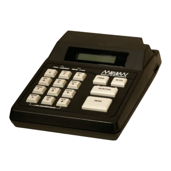
Page 9: Controls & Indicators
CONTROLS & INDICATORS 12:00 Freq: 01 Fire 1 PWR - LINE/SUP SEND - F1/F2 FREQ INTER ◄ ► SCROLL MONITOR PQRS WXYZ SEND MENU OPER Power/Volume Switch: On the right side of the TRC, there is a switch which acts as the power and volume switch. - Page 10 SEND: Pressing SEND will transmit the high-level guard tone for 120 msec, followed by the frequency tone for 40 msec, followed by the low-level guard tone that keys the radio with the voice and dialing riding over the low-level continuous tone. 0-9 Keys: Used in conjunction with the FREQ key these number keys can be used to select the frequency/function tone.
-
Page 11: Operation
OPERATION The TRC-1000 has 3 operating modes: Control Mode: This is the normal operating mode. It allows for remote control of a base station equipped with a tone remote adaptor such as Midian’s TTC-1. Call Mode: This mode is for encoding DTMF, 5-Tone, 2-Tone or Pulse Tone. - Page 12 Receiving: When a field radio keys up, the tone remote adaptor passes the voice down the line to the TRC. The voice will then be passed through to the internal speaker of the TRC. Intercom: Pressing the INTER key activates the Intercom function. Press and hold the INTER key to call other remotes on the line without keying the base station.
-
Page 13: Product Programming
PRODUCT PROGRAMMING The following is a map of the menu system in the TRC. Menu shortcut numbers are shown to the right of the menu item to which it applies. MAIN MENU PAGER SETUP <6> CALL <0> Profile 1 Profile 2 LOCK/UNLOCK Profile 3 USERS... - Page 14 Navigating the Menus Press the key MENU key while in Control to place the unit into Menu Mode. Upon entry to Menu Mode, you will be in the Main Menu. The top line of the display indicates this. The bottom line displays an item available for selection.
- Page 15 Entering Special DTMF Digits: The TRC supports the following special DTMF 'digits' in numeric entry mode: *, #, A, B, and C (D is not supported). These are entered using 2-key sequences as follows: * = * * # = * # A = * 1 B = * 2 C = * 3...
- Page 16 The following sections describe the various functions of the menu system. Shortcut keys are shown for those menu items that have shortcuts. Factory default settings are shown underlined. CALL <0> When the call command is selected you will be prompted to enter a user ID. You can either enter a unit ID or scroll right to enter into the database.
- Page 17 SETUP menu SET DATE/TIME <2> In order for the correct date and time to be displayed, the real-time clock must be set. Date: MMDDYYYY Time: HHMMSS SPEED DIAL SET <3> Speed Dial feature: When in Control Mode, the number keys <1> through <9> may be turned into speed dial keys by enabling this feature.
- Page 18 Line 2 or supervisor option disabled. Line 2 or supervisor option enabled. Follow Decode: Not used in the TRC-1000. Printer Option: The TRC, if ordered with the printer cable option, can log the pages to a serial device. The printer must have a print buffer and a standard RS-232 port. It must be configured for 9600 baud, 8 data bits, 1 stop bit and no parity.
- Page 19 PAGER SETUP <6> This section allows you define up to 10 different pager types. There are 10 pager profiles consisting of the fields described below. Each profile has a factory default setting intended as examples to follow. Profile Name field: This can be any alphanumeric string up to 14 characters. The name can be chosen based on the pager description such as ‘MOT PLAN L’...
- Page 20 0000 to 9999 milliseconds Pager Profiles and Defaults The following shows the factory default pager profile settings that allow the TRC-1000 to function ‘out of the box’. Please refer to section Error! Reference source not found. for more information. Profile 1: The factory default settings for this profile are as follows:...
- Page 21 Profile 5:The factory default settings for this profile are as follows: Profile Name: EIA 5-TONE Pager Type: 5/6-Tone Format: Tone Time: 0033 Tone Time: 0033 Profile 6: The factory default settings for this profile are as follows: Profile Name: EUROSIGNAL Pager Type: 5/6-Tone Format:...
- Page 22 SECURITY SETUP menu <7> Security: Allows the security option to be turned on and off. If off, the Lock/Unlock menus will not appear. O FF Disable security feature Enable security feature Password: Sets the password used to unlock the menu system when the security is enabled. Must be 4 numeric digits.
- Page 23 When to Send setting: Select when the frequency/function tone is sent. The options are as follows: AFTER SEND: The tone will be sent after high level guard tone every time the SEND key is pressed and ONLY after the SEND key is pressed. Therefore this setting is applicable only when the tone is used only for TX frequency control.
- Page 24 UTILITIES menu <9> Generate LLGT: Causes the TRC to generate low-level guard tone continuously until told to quit. This utility may be also be used to adjust the TX audio level. Press CLR to stop tone generation when done. Gen Test Tone: Causes the TRC to generate high level guard tone followed by a function tone. After that, a 1007 Hz test tone along with low-level guard tone will be generated for 10 seconds.
-
Page 25: Tone Signaling Formats
TONE SIGNALING FORMATS Signaling Format Compatibility In tone remote systems, the industry standard 2175 guard tone is filtered out by the tone remote adapter at the base station so that it is not heard over the air. This filter can affect signaling tones close to 2175 Hz. Tones within +/-70 Hz could be attenuated to a level such that they cannot be decoded by receiving equipment. - Page 26 Tone Encoding Tables Entering a user ID number, often called a CAP code, is straightforward for most of the encoding formats supported by the TRC. For example, when encoding DTMF or 5-tone, the digits 0-9 are simply typed in directly. Some formats do not allow for this straightforward approach.
-
Page 28: System Error Messages
SYSTEM ERROR MESSAGES DATABASE EMPTY Reason: An attempt was made to edit or delete a user when the database was empty. Solution: These functions do not apply when the database is empty. DATABASE FULL Reason: An attempt was made to add a user to the database and there is no more room. The maximum number of user aliases of 128 cannot be exceeded. - Page 29 SPEED DIAL EMPTY Reason: You have pressed a speed dial number, but there is no user associated with it. The user may have been deleted, or no association was ever made. Solution: Go to speed dial setup and associate a user in the database to the speed dial number. INVALID CAP CODE Reason: The number of digits in the CAP code are incorrect for the pager format being used.
-
Page 30: Theory Of Operation
THEORY OF OPERATION Initial Power-up: Upon power-up the TRC defaults to Frequency 1 when the [SEND] button is pressed. Analog Circuit RX Audio Input Path: RX audio from a tone remote adaptor at the remote site travels down the phone line to the RJ-11 line interface connector PL-1. - Page 31 Digital Circuit There are three microprocessors on the digital schematic page. U402 controls the keypad interface and also talks to the LCD. In addition it generates the keyboard beeps to the speaker amp, it controls the speaker mute when the handset is taken off-hook. Additionally, it controls the Line 2/Supervisor to the line relay on the analog page. Microprocessor U401 generates the Guard Tone, function tones and signaling tones on its B0-B7 port.
-
Page 32: Technical Notes
TECHNICAL NOTES No technical notes are available at this time. MIDIAN CONTACT INFORMATION MIDIAN ELECTRONICS, INC. 2302 East 22 Street Tucson, Arizona 85713 USA Toll-Free: 1-800-MIDIANS Main: 520-884-7981 E-mail: sales@midians.com Web: www.midians.com... - Page 33 OPTION 500 - MDC FORMAT OPTION 600 - FLEETSYNC FORMAT FOR NOTE INFORMATION, PLEASE SEE ANALOG PAGE. TRC SERIES TRC SERIES TRC SERIES FILE NAME FILE NAME FILE NAME MIDIAN ELECTRONICS, INC. MIDIAN ELECTRONICS, INC. MIDIAN ELECTRONICS, INC. TRC-500 TRC-500 TRC-500 DATE DATE DATE NOV.
- Page 34 TRC SERIES TRC SERIES TRC SERIES FILE NAME FILE NAME FILE NAME 4.7K 4.7K 6.2K 6.2K MIDIAN ELECTRONICS, INC. MIDIAN ELECTRONICS, INC. MIDIAN ELECTRONICS, INC. TRC-500 TRC-500 TRC-500 NOTE5 - ONLY INSTALLED WHEN LCD OPTION REQUIRED. Q304 Q304 ANALOG ANALOG...
Need help?
Do you have a question about the TRC-1000 and is the answer not in the manual?
Questions and answers