Table of Contents
Advertisement
Quick Links
M
6
V
L
Q
G
r
a
n
d
M
6
V
L
Q
G
r
a
n
d
M
6
V
L
Q
G
r
a
n
d
FCC Information and Copyright
This equipment has been tested and found to comply with the limits of a
Class B digital device, pursuant to Part 15 of the FCC Rules. These limits
are
designed
to
provide
reasonable
protection
against
harmful
interference in a residential installation. This equipment generates, uses
and can radiate radio frequency energy and, if not installed and used in
accordance with the instructions, may cause harmful interference to radio
communications. There is no guarantee that interference will not occur in
a particular installation.
The vendor makes no representations or warranties with respect to the
contents here of and specially disclaims any implied
of
warranties
merchantability or fitness for any purpose. Further the vendor reserves
the right to revise this publication and to make changes to the contents
here of without obligation to notify any party beforehand.
Duplication of this publication, in part or in whole, is not allowed without
first obtaining the vendor's approval in writing.
The content of this user's manual is subject to be changed without notice
and we will not be responsible for any mistakes found in this user's
manual. All the brand and product names are trademarks of their
respective companies.
i
Advertisement
Table of Contents

Related Manuals for Biostar M6VLQ Grand


Summary of Contents for Biostar M6VLQ Grand
- Page 1 FCC Information and Copyright This equipment has been tested and found to comply with the limits of a Class B digital device, pursuant to Part 15 of the FCC Rules. These limits designed provide reasonable protection against harmful interference in a residential installation. This equipment generates, uses and can radiate radio frequency energy and, if not installed and used in accordance with the instructions, may cause harmful interference to radio communications.
-
Page 2: Table Of Contents
LAYOUT OF M6VLQ GRAND ...1 COMPONENT INDEX ...2 ENGLISH ...3 M6VLQ Pro Features ... 3 Package contents ... 4 How to setup Jumper ... 5 CPU Installation ... 5 DIMM Modules: DIMM1/ DIMM2 ... 6 Jumpers, Headers, Connectors & Slots... 7 ESPAÑOL...12... -
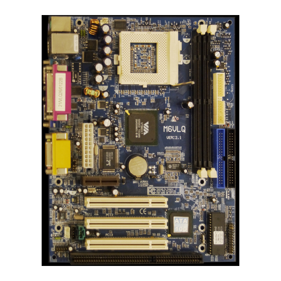
Page 3: Layout Of M6Vlq Grand
Layout of M6VLQ Grand ※NOTE: ●represents the first pin. -
Page 4: Component Index
Component Index A. Power Source Selection for Keyboard and mouse (JKBV1) B. Power Source Selection for USB (JUSBV1) C. Back Panel Connector D. ATX Power Connector (JATXPWR1) E. Front Audio Header (JAUDIO1) F. CD Audio-In Header (JCDIN2) G. CD Audio-In Header (JCDIN1) H. -
Page 5: English
English M6VLQ Pro Features A. Hardware Provides Socket 370. Supports Celeron™ processor PPGA (FC-PGA & FC-PGA2) and the Pentium® III Micro-Processor (FC-PGA & FC-PGA2) and VIA C3 Ezra and Ezra-T Samuel 2 for high-end workstations and servers. Front Side Bus at 66/100/133 MHz. Chipset North Bridge: VIA CLE266 CE. -
Page 6: Package Contents
On Board Peripherals a. Rear side 1 serial port. 1 VGA port. 1 parallel port. (SPP/EPP/ECP mode) 1 audio port in horizontal position. 1 LAN jack. PS/2 mouse and PS/2 keyboard. 2 USB2.0 ports. b. Front Side 1 floppy port supports 2 FDDs with 360K, 720K, 1.2M, 1.44M and 2.88Mbytes. 4 USB2.0 ports. -
Page 7: How To Setup Jumper
How to setup Jumper The illustration shows how jumpers are setup. When the Jumper cap is placed on pins, the jumper is “close”. If no jumper cap is placed on the pins, the jumper is ”open”. The illustration shows a 3-pin jumper whose pin 1and 2 are “close” when jumper cap is placed on these 2 pins. -
Page 8: Dimm Modules: Dimm1/ Dimm2
CPU Fan Header: JCFAN1 Pin No. JCFAN1 System Fan Header: JSFAN1 Pin No. JSFAN1 DIMM Modules: DIMM1/ DIMM2 DRAM Access Time: 2.5V Unbuffered DDR 200/266 MHz Type required. DRAM Type: 64MB/ 128MB/ 256MB/ 512MB/ 1GB DIMM Module (184 pin) Total Memory Size with Unbuffered DIMMs DIMM Socket DDR Module Location... -
Page 9: Jumpers, Headers, Connectors & Slots
The first hard drive should always be connected to IDE1. Peripheral Component Interconnect Slots: PCI 1-3 This motherboard is equipped with 3 standard PCI slots. PCI stands for Peripheral Component Interconnect, and it is a bus standard for expansion cards. This PCI slot is designated as 32 bits. -
Page 10: Front Panel Connector: Jpanel1
Front Panel Connector: JPANEL1 PWR_LED JPANEL1 (+) (-) HLED Assignment Function Speaker Connector Speaker HDD LED (+) Hard Drive HDD LED (-) Ground Reset Button Reset Control IrDA Connector IRTX Front USB Header: JUSB1/2 Assignment +5V(fused) USBP4- USBP4+ JUSB1/2 Power Source Selection for Keyboard/ Mouse: JKBV1 JKBV1 Assignment Pin 1-2 close... - Page 11 +5V Standby Voltage Pin 2-3 close Note: In order to support this function “Power-on the system via keyboard and mouse”, “JKBV1” jumper cap should be placed on pin 2-3. Power Source Selection for USB: JUSBV1/ JUSBV2 JUSBV1/JUSBV2 Assignment Pin 1-2 close +5V Standby Voltage Pin 2-3 close...
- Page 12 The following procedures are for resetting the BIOS password. It is important to follow these instructions closely. ※ Clear CMOS Procedures: 1. Remove AC power line. 2. Set the jumper to “Pin 2-3 Close”. 3. Wait for five seconds. 4. Set the jumper to “Pin 1-2 Close”. 5.
- Page 13 Digital Audio Connector: JSPDIF1 JSPDIF1 Wake On LAN Header: JWOL1 JWOL1 Back Panel Connectors JUSBLAN1 JPRNT1 PS/2 (Optional) Mouse Parallel Port PS/2 COM1 Keyboard JCOM1 JKBMS1 Assignment SPDIF_OUT Ground Assignment +5V Standby Ground Wake up JGAME1 Game Port VGA1 Speaker JVGA1 Line In...
-
Page 14: Español
Español Características del M6VLQ Pro A. Hardware Proporciona Socket 370. Soporta procesador Celeron™ PPGA (FC-PGA & FC-PGA2) y Pentium® III Micro-Procesador (FC-PGA & FC-PGA2) y VIA C3 Ezra and Ezra –T Samuel 2 para estaciones de trabajo y servidores de alta capacidad. Front Side Bus a 66/100/133 MHz. -
Page 15: Contenido Del Paquete
Periféricos Onboard a. Parte Trasera 1 puerto en serie. 1 puerto VGA. 1 puerto paralelo. (modos SPP/EPP/ECP) 1 puerto de audio en posición horizontal. 1 LAN jack. Ratón PS/2 y teclado PS/2. 2 puertos USB2.0. b. Parte Delantera 1 puerto para disquetera soportando 2 FDDs de 360K, 720K, 1.2M, 1.44M y 2.88Mbytes. -
Page 16: Cómo Instalar Un Puente
Cómo instalar un Puente La ilustración muestra cómo instalar un puente. Cuando el Jumper Cap está ubicado en los contactos, el puente está en “close”. Si no hay Jumper Cap ubicado en los contactos, el puente está en ”open”. La siguiente ilustración muestra un contacto 3 en el que los contactos 1 y 2 están “close”... -
Page 17: Módulos Dimm: Dimm1/ Dimm2
Cabezal del Sistema de Ventilación del CPU: JCFAN1 Conrtacto No. JCFAN1 Cabezal del Sistema de Ventilación: JSFAN1 Contacto No. JSFAN1 Módulos DIMM: DIMM1/ DIMM2 DRAM Tiempo de Acceso: 2.5V Unbuffered DDR 200/266 MHz Tipo requerido. DRAM Tipo: 64MB/ 128MB/ 256MB/ 512MB/ 1GB Módulo DIMM (184 contactos) Total del Tamaño de Memoria Unbuffered DIMMs Localización Módulo DDR... -
Page 18: Puentes, Cabezales, Conectores Y Ranuras
Puentes, Cabezales, Conectores y Ranuras Conector de Disquetera: FDD1 La placa madre proporciona un conector estándar para disquete que soporta disquetera de 360K, 720K, 1.2M, 1.44M y 2.88M. Éste conector utiliza cables proporcionados por el disquete. Conector del Disco Duro: IDE1/ IDE2 La placa madre tiene un controlador de 32-bit PCI IDE que proporciona Modo PIO 0~5, Bus Master, y funcionalidad Ultra DMA 33/ 66/ 100. - Page 19 Conector del Panel Frontal: JPANEL1 JPANEL1 Contacto Asignación Función Conector del Altavoz Altavoz HDD LED (+) del Disco Duro HDD LED (-) Tierra Botón de Reinicio Control de Reinicio Conector IrDA IRTX Cabezal Frontal USB: JUSB1/2 Contactos JUSB1/2 PWR_LED ON/OFF (+) (-) HLED Contacto...
-
Page 20: Fuente De Corriente Selección Para Teclado/Ratón
Fuente de Corriente Selección para Teclado/ Ratón: JKBV1 JKBV1 Asignación Contacto 1-2 close Voltaje Standby +5V Contacto 2-3 close Nota: Para soportar la función “Encendiendo el sistema por medio del teclado y ratón”, el jumper cap del “JKBV1” debe ser ubicado en el contacto 2-3. - Page 21 Puente de Borrar CMOS: JCMOS1 JCMOS1 Contacto 1-2 Close Contacto 2-3 Close Los siguientes procesos son para reiniciar la contrasena del BIOS. Es importante que siga los s i g u i e n t e s p a s o s c u i d a d o s a m e n t e . ※...
- Page 22 Cabezal de Audio del Panel Frontal: JAUDIO1 Contactos Asignación Entrada del Mic Corriente del Mic Salida de Línea Derecho/ Salida del Altavoz Derecho Reservado Salida de Línea Izquierdo/ Salida del Altavoz Izquierdo Conector Digital de Audio: JSPDIF1 JSPDIF1 Conectores del Panel Trasero JUSBLAN1 Raton (Opcional)
-
Page 23: Watchdog Technology
Watchdog Technology It is important to know that when overclocking, the system can be at a vulnerable state. Therefore, the BIOSTAR Watchdog Technology was designed to protect your PC under dangerous over-clock situations. Any over-clocking that reaches the threshold settings, the Watchdog Technology will disable your system from rebooting in the BIOS setting. -
Page 24: Warpspeeder
WarpSpeeder Introduction [ WarpSpeeder™ ], a new powerful control utility, features three user-friendly functions including Overclock Manager, Overvoltage Manager, and Hardware Monitor. With the Overclock Manager, users can easily adjust the frequency they prefer or they can get the best CPU performance with just one click. The Overvoltage Manager, on the other hand, helps to power up CPU core voltage and Memory voltage. -
Page 25: Installation
Installation Execute the setup execution file, and then the following dialog will pop up. Please click “Next” button and follow the default procedure to install. When you see the following dialog in setup procedure, it means setup is completed. If the “Launch the WarpSpeeder Tray Utility” checkbox is checked, the Tray Icon utility and [WarpSpeeder™] utility will be automatically and immediately launched after you click “Finish”... -
Page 26: Usage
Usage The following figures are just only for reference, the screen printed in this user manual will change according to your motherboard on hand. [WarpSpeeder™] includes 1 tray icon and 5 panels: 1. Tray Icon: Whenever the Tray Icon utility is launched, it will display a little tray icon on the right side of... - Page 27 This utility is responsible for conveniently invoking [WarpSpeeder™] Utility. You can use the mouse by clicking the left button in order to invoke [WarpSpeeder™] directly from the little tray icon or you can right-click the little tray icon to pop up a popup menu as following figure.
- Page 28 3. Voltage Panel Click the Voltage button in Main Panel, the button will be highlighted and the Voltage Panel will slide out to up as the following figure. In this panel, you can decide to increase CPU core voltage and Memory voltage or not. The default setting is “No”.
- Page 29 4. Overclock Panel Click the Overclock button in Main Panel, the button will be highlighted and the Overclock Panel will slide out to left as the following figure.
- Page 30 Overclock Panel contains these features: a. “–3MHz button”, “-1MHz button”, “+1MHz button”, and “+3MHz button”: provide user the ability to do real-time overclock adjustment. Warning: Manually overclock is potentially dangerous, especially when the overclocking percentage is over 110 %. We strongly recommend you verify every speed you overclock by click the Verify button.
- Page 31 “Auto-overclock button”: User can click this button and [ WarpSpeeder™ ] will set the best and stable performance and frequency automatically. [ WarpSpeeder™ ] utility will execute a series of testing until system fail. Then system will do fail-safe reboot by using Watchdog function. After reboot, the [ WarpSpeeder™ ] utility will restore to the hardware default setting or load the verified best and stable frequency according to the Recovery Dialog’s setting.
- Page 32 5. Hardware Monitor Panel Click the Hardware Monitor button in Main Panel, the button will be highlighted and the Hardware Monitor panel will slide out to left as the following figure. In this panel, you can get the real-time status information of your system. The information will be refreshed every 1 second.
- Page 33 Note: Because the overclock, overvoltage, and hardware monitor features are controlled by several separate chipset, [ WarpSpeeder™ ] divide these features to separate panels. If one chipset is not on board, the correlative button in Main panel will be disabled, but will not interfere other panels’ functions.
-
Page 34: Studiofun! Tm (Optional)
StudioFun! (Optional) Introduction StudioFun! is a media-player based on optimized GNU/Linux distribution to bring a “Room Theater” experience into life. It plays DVD, VCD, MP3, Audio CD and other multimedia. Furthermore, Users can take snapshots of video and customize the saved images as screensavers or photo slideshows. Of course, the images can be stored in USB mass storage devices like flash disks and USB floppy disks. -
Page 35: Trouble Shooting
Trouble Shooting PROBABLE No power to the system at all Power light don’t illuminate, fan inside power supply does not turn on. Indicator light on keyboard does not turn on PROBABLE System inoperative. Keyboard lights are on, power indicator lights are lit, hard drive is spinning. -
Page 36: Solución De Problemas
Solución de Problemas CAUSA PROBABLE No hay corriente en el sistema. La luz de corriente no ilumina, ventilador dentro de la fuente de alimentación apagada. Indicador de luz del teclado apagado. CAUSA PROBABLE Sistema inoperativo. Luz del teclado encendido, luz de indicador de corriente iluminado, disco rígido está... - Page 37 08/13/2003...
Need help?
Do you have a question about the M6VLQ Grand and is the answer not in the manual?
Questions and answers