Table of Contents
Advertisement
Quick Links
Advertisement
Table of Contents

Related Manuals for Biostar M6VCG

Summary of Contents for Biostar M6VCG
- Page 1 User manual Motherboard M6VCG...
- Page 2 Federal Communications Commission (F.C.C) Statement -This device complies with Part 15 of the FCC Rules. Operation of this device is subject to the following two conditions: (1) this device may not cause harmful interference, and (2) this device must accept any interference received, including interference that may cause undesired operation. -Accessories: This device has been tested and found to comply with the limits of a Class B digital device, the accessories associated with this equipment are as follows: 1.
-
Page 3: Table Of Contents
Contents CONTENTS Introduction ..........................1 1 Motherboard Description .....................1 1.1 Features................................. 1 1.1.1 Hardware............................... 1 1.1.2 Software ..............................3 1.2 Motherboard Installation ..........................4 1.2.1 Layout of Motherboard ......................... 4 1.3 Motherboard Connectors ..........................5 1.3.1 Front Panel Connectors: PANEL1 ......................6 1.3.2 ATX 20-pin Power Connector: ...................... - Page 4 Contents 2.5 Integrated Peripherals ..........................26 2.6 Power Management Setup .......................... 28 2.7 PnP/PCI Configurations..........................30 2.8 PC Health Status ............................32 2.9 Frequency Control ............................33 2.10 Load Optimized Defaults.......................... 33 2.11 Set Supervisor/User Password ........................34 2.12 Save & Exit Setup............................. 34 2.13 Exit Without Saving..........................
-
Page 5: Introduction
Motherboard Description Introduction System Overview Thanks for buying this product! This manual was written to help you start using this product as quickly and smoothly as possible. Inside you will find adequate explanations to solve most problems. In order for this reference material to be of greatest use, refer to the “expanded table of contents”... - Page 6 Motherboard Description ™ − Supports booting from LS-120 “SuperDisk” or iomega ZIP disk. Super I/O Built-in onboard − Support one multi-mode Parallel Port. (1) Standard & Bidirection Parallel Port (SPP). (2) Enhanced Parallel Port (EPP). (3) Extended Capabilities Port (ECP). −...
-
Page 7: Software
Motherboard Description Full Featured Accerated Graphics Port (AGP) Controller − Synchronous and pseudo-synchronous with the CPU bus with optimal skew control. − AGP v2.0 compliant. − Supports SideBand Addressing (SBA) mode (non-multiplexed address / data). − Supports 266 MHZ 4x mode for AD and SBA signaling. −... -
Page 8: Motherboard Installation
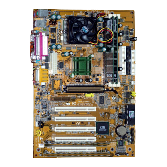
Motherboard Description 1.2 Motherboard Installation 1.2.1 Layout of Motherboard Model No.M6VCG & Mouse USB1 CN7B1 CN7A1 VT82C694X CN7C1 J20A1 POWER1 JWOL1 AGP1 AGP SLOT JFREQ1 AMR SLOT AMR1 PCI BUS SLOT PCI1 BIOS PCI BUS SLOT PCI2 BAT1 PCI BUS SLOT... -
Page 9: Motherboard Connectors
Motherboard Description 1.3 Motherboard Connectors B C D A. Back panel I/O Connectors K. Front Panel CONN. (PANEL1) B. AGP BUS Slot (AGP1) L. CMOS Function Selection (JBAT1) C. CPU Frequency Selection (JP1) M. System Fan Connector (J5) D. AMR Slot (AMR1) N. -
Page 10: Front Panel Connectors: Panel1
Motherboard Description 1.3.1 Front Panel Connectors: PANEL1 S M I H L E D S P K P O W E R L E D P W R R S T Assignment Function Assignment Function Speaker Speaker Ground Ground Ground Connector Sleep Switch Power LED(+) -
Page 11: Atx 20-Pin Power Connector
Motherboard Description SMI (Sleep/Resume Switch) When APM is enabled in the system BIOS, and the operating system’s APM driver is loaded, the system can enter sleep (standby) mode in one of the following ways: • Optional front panel SMI button •... -
Page 12: Hard Disk Connectors: Ide1 / Ide2
Motherboard Description 1.3.3 Hard Disk Connectors: IDE1 / IDE2 The motherboard has a 32-bit Enhanced PCI IDE Controller that provides PIO Mode 0~4, Bus Master, and Ultra DMA 33 / 66 functionality. It has two HDD connectors IDE1 (primary) and IDE2 (secondary). You can connect up to four hard disk drives, a CD-ROM, a 120MB Floppy (reserved for future BIOS) and other devices to IDE1 and IDE2. -
Page 13: Usb Connectors: Usb1
Motherboard Description 1.4.2 USB Connectors: USB1 The motherboard provides a UHCI (Universal Host Controller Interface) Universal Serial Bus Roots for attaching USB devices such as keyboard, mouse and other USB devices. You can plug the USB Devices directly into this connector. USB1 Stacked USB Connectors Signal Name... -
Page 14: Serial And Parallel Interface Ports
Motherboard Description 1.5 Serial and Parallel Interface Ports This system comes equipped with two serial ports and one parallel port. Both types of interface ports will be explained in this chapter. The Serial Interface Port : COM1 / COM2 The serial interface port is sometimes referred to as an RS-232 port or an asynchronous communications port. - Page 15 Motherboard Description signals and the other device is not. This can usually be resolved by wiring the RTS, CTS, and DCD pins together. Serial Ports/COM Ports The two serial ports on the computer are called COM1 and COM2, respectively. If you wish, two more serial ports can be added onto the computer using optional hardware.
-
Page 16: Cpu Installation
Motherboard Description 1.6 CPU Installation 1.6.1 CPU Installation Procedure: Socket 370 Pull the lever sideways away from the socket then raise the lever up to a 90-degree angle. Locate Pin A in the socket and look for the white dot or cut edge in the CPU. Match Pin A with the white dot/cut edge then insert the CPU. -
Page 17: Cpu Jumper Settings
Motherboard Description 1.6.2 CPU Jumper Settings JFREQ1 1.6.2.1 CPU Ratio Selection: JFREQ1 JFREQ1 RATIO x 2.0 CLOSE CLOSE CLOSE CLOSE CLOSE CLOSE OPEN CLOSE x 2.5 CLOSE OPEN CLOSE CLOSE x 3.0 x 3.5 CLOSE OPEN OPEN CLOSE x 4.0 OPEN CLOSE CLOSE... -
Page 18: Jumper Settings
Motherboard Description 1.7 Jumper Settings The jumper has two or more pins that can be covered by a plastic jumper cap, allowing you to select different system options. JWOL1 JBAT1 1.7.1 System Fan Connector: J5 Pin No. Assignment Sense +12 V Control Signal 1.7.2 CPU Fan Connector: J6 Pin No. -
Page 19: Cmos Function Selection: Jbat1
Motherboard Description 1.7.4 CMOS Function Selection: JBAT1 JBAT1 Assignment Normal Operation (default) 1-2 Closed Clear CMOS Data (*Note) 2-3 Closed Onboard Battery Disabled Open Note: Please follow the procedure as below to clear CMOS Data. Note: Please follow the procedure as below to clear BIOS Password if your password is lost or forgotten. -
Page 20: Dram Installation
Motherboard Description 1.8 DRAM Installation 1.8.1 DIMM DRAM Access Time : 3.3V Unbuffered SDRAM PC66, PC100 & PC133 Type required. DRAM Type : 8MB/16MB/32MB/64MB/128MB/256MB DIMM Module (168pin) Total Bank 0 Bank 1 Bank 2 Memory Size (MB) DIMM1 DIMM2 DIMM3 8M x 1 pc ---- ----... -
Page 21: How To Install A Dimm Module
Motherboard Description 1.8.2 How to install a DIMM Module The DIMM socket has a “ ast c Safety Tab and the DIMM memory module has an “asymmetrical notch”, so the DIMM memory module can only fit in one direction. Push the tabs out. Insert the DIMM memory modules into the socket at 90-degree angle, then push down vertically so that it will fit into place. -
Page 22: Audio Subsystem
Motherboard Description 1.9 Audio Subsystem 1.9.1 CD Audio-In Connectors: J7/J8 Pin No. of J7 Assignment Left Channel Input CD_GND Right Channel Input CD_GND Pin No. of J8 Assignment Right Channel Input Left Channel Input 1.9.2 AUX Audio in Connector: J10 (Optional) Pin No. -
Page 23: Bios Setup
BIOS Setup 2. BIOS Setup Introduction This manual discussed Award™ Setup program built into the ROM BIOS. The Setup program allows users to modify the basic system configuration. This special information is then store in battery-backed RAM so that it retains the Setup information when the power is turned off. The Award BIOS™... -
Page 24: Main Menu
BIOS Setup Keystroke Function Up arrow Move to previous item Down arrow Move to next item Left arrow Move to the item on the left (menu bar) Right arrow Move to the item on the right (menu bar) Main Menu: Quit without saving changes Submenus: Exit Current page to the next higher level menu Move Enter Move to the item you desired... -
Page 25: Standard Cmos Features
BIOS Setup PC Healte Status This setup page is the System auto detect Temperature, voltage, fan speed. Frequency Control This setup page is the System auto detect CPU Host Clock as default or setup by SPD on DIMM. Load Optimized Defaults These settings are more likely to configure a workable computer when something is wrong. - Page 26 BIOS Setup Main Menu Selections This table shows the selections that you can make on the Main Menu. Item Options Description Date DD YYYY Set the system date. Note That the ‘Day’ automatically changes when you set the date. IDE Primary Master Options are in its sub Press <Enter>...
-
Page 27: Advanced Bios Features
BIOS Setup 2.3 Advanced BIOS Features #" Figure 3. Advanced BIOS Setup CMOS Setup Utility-Copyright (C ) 1984-2000 Award Software Advanced BIOS Features Disabled Virus Warning Item Help CPU Internal Cache Enabled External Cache Enabled Menu Level CPU L2 Cache ECC Checking Enabled Processor Number Feature Disabled... - Page 28 BIOS Setup Quick Power On Self Test This category speeds up Power on Self-Test (POST) after you power up the computer. If it is set to Enable, BIOS will shorten or skip some check items during POST. Enabled (default) Enable quick POST Disabled Normal POST First /Second/Third/Other Boot Device...
-
Page 29: Advanced Chipset Features
BIOS Setup 2.4 Advanced Chipset Features This section allows you to configure the system based on the specific features of the installed chipset. This chipset manages bus speeds and access to system memory resources, such as DRAM and the external cache. -
Page 30: Integrated Peripherals
BIOS Setup Memory Parity/ECC Check You can reserve this area of system memory for ISA adapter ROM. When this area is reserved, it cannot be cached. The user information of peripherals that need to use this area of system memory usually discusses their memory requirements. - Page 31 BIOS Setup Primary / Secondary Master / Slave PIO The IDE PIO (Programmed Input / Output) fields let you set a PIO mode (0-4) for each of the IDE devices that the onboard IDE interface supports. Modes 0 through 4 provide successively increased performance. In Auto mode, the system automatically determines the best mode for each device.
-
Page 32: Power Management Setup
BIOS Setup ECP Mode Use DMA Select a DMA Channel for the port. The Choice: 3 (default). Parallel Port EPP type Select a DMA Channel for the port. The Choices: EPP1.9 (default), EPP1.7. Game Port (200-207H) Change the joystick connects port address. 2.6 Power Management Setup The Power Management Setup allows you to configure you system to most effectively save energy while operating in a manner consistent with your own style of computer use. - Page 33 BIOS Setup PM Control by APM This function set Power Management control by Advance Power Management. Yes (default) Video Off Option This determines the manner in which the monitor is blanked. Suspend Off (default) During Suspend mode, the monitor will be turned off. All Modes During All modes, the monitor will be turned off.
-
Page 34: Pnp/Pci Configurations
BIOS Setup Date (of Month) /Time (hh:mm:ss) You could set the date (of month) and timer (hh:mm:ss), any event occurring at will awaken a system witch has been powered down. 2.7 PnP/PCI Configurations This section describes configuring the PCI bus system. PCI, or Personal Computer Interconnect, is a system which allows I/O devices to operate at speeds nearing the speed the CPU itself uses when communicating with its own special components. - Page 35 BIOS Setup DMA-0 assigned to: PCI / ISA PnP DMA-1 assigned to: PCI / ISA PnP DMA-3 assigned to: PCI / ISA PnP DMA-5 assigned to: PCI / ISA PnP DMA-6 assigned to: PCI / ISA PnP DMA-7 assigned to: PCI / ISA PnP The above settings will be shown on the screen only if “Manual”...
-
Page 36: Pc Health Status
BIOS Setup 2.8 PC Health Status #" Figure 8. Frequency/Voltage Control CMOS Setup Utility-Copyright (C ) 1984-2000Award Software PC Health Status Current CPU Temp Item Help Current System Temp System FAN Speed CPU FAN Speed Menu Leve Vcore 2.5V 3.3V : Move Enter :Select +/-/PU/PD :Value F10 :Save ESC :Exit F1 :General Help F5 :Previous Values F6 :Fail-Safe Defaults... -
Page 37: Frequency Control
BIOS Setup 2.9 Frequency Control #" Figure 9. Frequency/Voltage Control CMOS Setup Utility-Copyright (C ) 1984-2000Award Software Frequency Control CPU Host Clock (CPU/PCI) default Item Help Manual Level : Move Enter :Select +/-/PU/PD :Value F10 :Save ESC :Exit F1 :General Help F5 :Previous Values F6 :Fail-Safe Defaults F7 : Optimized Defaults... -
Page 38: Set Supervisor/User Password
BIOS Setup 2.11 Set Supervisor/User Password #" Figure 11. Set Supervisor/User Password CMOS Setup Utility-Copyright (C ) 1984-1999 Award Software Standard CMOS Features PC Health Status Advanced BIOS Features Load Optimized Defaults Advanced Chipset Features Set Supervisor Password Integrated Peripherals Set User Password Power Management Setup Save &... -
Page 39: Exit Without Saving
BIOS Setup 2.13 Exit Without Saving #" Figure 13. Exit Without Saving CMOS Setup Utility-Copyright (C ) 1984-2000 Award Software Standard CMOS Features PC Health Status Advanced BIOS Features Load Optimized Defaults Advanced Chipset Features Set Supervisor Password Integrated Peripherals Set User Password Power Management Setup Set User Password... - Page 40 08/03/2000 MADE IN TAIWAN R.O.C.
Need help?
Do you have a question about the M6VCG and is the answer not in the manual?
Questions and answers