Table of Contents
Advertisement
Quick Links
IDX-OM-O004E-A
Initial release: February 2011
2th edition: November 2016
PRODUCT NAME
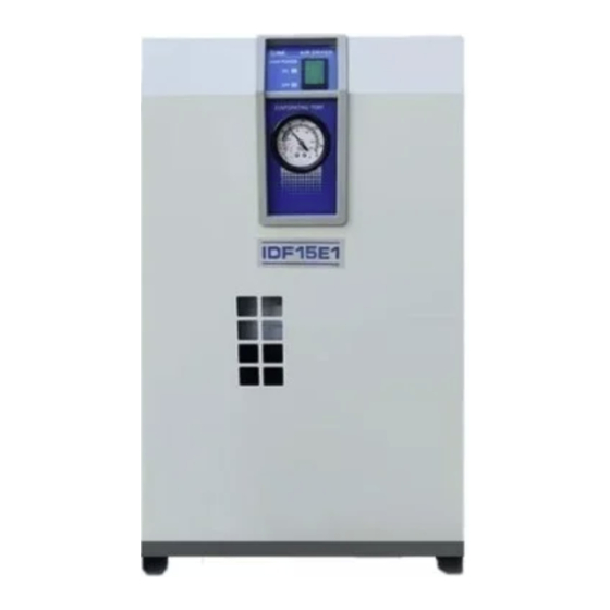
Refrigerated Air Dryer
MODEL
IDF15E1-10 (-A,C,K,L,M,R,S,T)
IDF15E1-20 (-A,C,K,L,M,R,T)
This manual is intended to explain the installation and operation of the product.
Only people who understand the basic operation of the product, or have basic
knowledge and ability to handle industrial machinery, are allowed to work on the
product.
Keep this manual available whenever necessary.
© 2016 SMC CORPORATION All Rights Reserved.
Advertisement
Table of Contents

Related Manuals for SMC Networks IDF15E1-10


Summary of Contents for SMC Networks IDF15E1-10
- Page 1 2th edition: November 2016 PRODUCT NAME Refrigerated Air Dryer MODEL IDF15E1-10 (-A,C,K,L,M,R,S,T) IDF15E1-20 (-A,C,K,L,M,R,T) This manual is intended to explain the installation and operation of the product. Only people who understand the basic operation of the product, or have basic knowledge and ability to handle industrial machinery, are allowed to work on the product.
- Page 2 Foreword Thank you for purchasing SMC’s refrigerant type air dryer (hereinafter referred to as the “product”). For safety and long life of the product, be sure to read this Operation Manual (hereinafter referred to as the “manual”) and clearly understand the contents. ●...
-
Page 3: Table Of Contents
Table of Contents To Customers Chapter i Safety Instructions i . 1 Warning: Before using this product ..........i - 1 i .1. 1 Danger, Warning and Caution ..............i - 1 i . 2 Hazard classification and locations of hazard labels .... - Page 4 Chapter 5 Troubleshooting 5 . 1 Troubleshooting ..................5 - 1 Chapter 6 References 6 . 1 Specification table .................. 6 - 1 6 . 2 Refrigerant with GWP reference ............6 - 1 6 . 3 Outer dimensions ................... 6 - 2 6 .
-
Page 5: Chapter I Safety Instructions
i Safety Instructions i Safety Instructions Before using the product be sure to read and understand all the important actions highlighted in this manual. i.1 Warning: Before using this product This chapter is intended to specifically describe the safety related issues for handling the product. Read this before handling the product. -
Page 6: Hazard Classification And Locations Of Hazard Labels
i Safety Instructions Warning “Warning” indicates a hazard with a medium level of risk which will result in death or serious injury if an operator does not follow the specified procedures during the operation or maintenance of the product or does not follow the instructions necessary to avoid it. Caution “Caution”... -
Page 7: Hazards
i Safety Instructions i.2.1 Hazards The hazards inherent to the product are as follows. Warning related to electricity The product is operated at a high voltage and can cause electrical shock internally. This risk is indicated with the mark in addition to “Danger”, “Warning” and “Caution” on the product or in this manual. -
Page 8: Warning Related To Pneumatic Circuit
i Safety Instructions i.2.5 Warning related to pneumatic circuit Warning Be sure to release compressed air from the product and ensure the internal pressure is zero before replacing or cleaning the parts of the product. If the compressed air is left in the product, when some part is loosened, it may cause sudden lurching or other unexpected accidents. -
Page 9: Caution Related To Refrigerant
i Safety Instructions i.2.7 Caution related to refrigerant Caution - The product uses hydro-fluorocarbon type refrigerant (HFC). - The product is categorized as category 1 under the fluorocarbon recovery and destruction law in Japan. The release of refrigerant into the atmosphere is banned by law. When the product is serviced, the refrigerant must be recovered using “refrigerant recovery equipment”... -
Page 10: Caution Related To Handling
i Safety Instructions i.2.8 Caution related to handling Warning - Fully read and understand the contents of the hazard labels. - Do not peel or rub off the hazard labels. - Carefully confirm where the hazard labels are affixed. CAUTION 注 意 1 Read manual before operation. -
Page 11: Waste Disposal
i Safety Instructions i.3 Waste disposal When disposing of the product, recover the refrigerant and compressor oil contained in the refrigerant circuit. Caution - The product uses hydro-fluorocarbon type refrigerant (HFC). - The product is categorized as category 1 under the fluorocarbon recovery and destruction law in Japan. -
Page 12: Limited Warranty And Disclaimer / Compliance Requirements
i Safety Instructions i.4 Limited warranty and Disclaimer / Compliance Requirements The product used subject to the following “Limited warranty and Disclaimer“ and “Compliance Requirements. Read and accept them before using the product. Limited warranty and Disclaimer The warranty period of the product is 1 year in service or 1.5 years after the product is delivered. Also, the product may have specified durability, running distance or replacement parts. -
Page 13: Chapter 1 Name And Function Of Parts
1. Name and Function of Parts 1 Name and Function of Parts 1.1 Name and function of parts Ventilation air outlet Hot air will be exhausted from condenser by fan. No obstacles Switch with lamp shall be allowed to place on top The switch to start and stop the product, of it or even close the grille. - Page 14 1. Name and Function of Parts IDF15E1-10 (100V AC specification) Front Air outlet piping A port to exhaust air. Ventilation air inlet Air inlet piping Breathe in cooling air from A port to supply air. this grille. Do not bung up with wall and so on.
-
Page 15: Chapter 2 Transportation And Installation
2. Transportation and installation 2 Transportation and installation Warning - Use the product in an appropriate manner, and pay attention to safety, particularly physical safety of operators, during the installation, operation, maintenance and checks of the product. - When the product is used for a critical facility or equipment, prepare a spare product or alternative machine in case of stoppage of the product due to the operation of the protective equipment or the failure of the product itself. -
Page 16: Installation
2. Transportation and installation 2.2 Installation 2.2.1 Environment (1) Do not use or store the product under the following conditions, as these may cause breakage of the product as well as a failure of the product to operate. • In an environment where the product will come into direct contact with rain, wind and snow or with a lot of moisture (relative humidity 85% or more). -
Page 17: Fixing Of Product
2. Transportation and installation 2.2.2 Fixing of product Mount the product on a flat and stable floor with no vibrations. - Refer to “6.2 Outer dimensions” on page 6-2 for dimensions. - Use the foundation bolts to prevent the product from falling over. The foundation bolts are available separately as a set. -
Page 18: Pneumatic Piping
2. Transportation and installation 2.2.3 Pneumatic piping - Piping to the compressed air inlet and outlet should be connected with a union of fitting so that it can be removed. - Pressing the hexagonal fitting with screw wrench and so on, connect the air piping fittings to the body. - When mounting any part such as an air filter on the fitting at the compressed air inlet or outlet port, support the part to prevent excessive force from being applied to the product. -
Page 19: Electric Wiring
[Wiring of power supply] There are two methods depends on model (specified power). IDF15E1-10 (100V AC specification) Insert the power plug into an outlet of AC100V. ∗ Be sure to install an round fault circuit interrupter to the power supply. (To be prepared by the user.) [Sensitivity of leak current: 30mA or less, Rated current: 10A] Do not extend the power cable using power strip and so on. -
Page 20: Reinstallation Of The Product
2. Transportation and installation Terminal block (refer to “1.1 Name and function of parts” for details). Connect the power cable and the ground to the terminal block. The connection size is M3. Be sure to use a round crimped terminal. Applicable crimped terminal width: 6.5mm or less [Wiring procedure] 1. - Page 21 2. Transportation and installation Residual compressed air pressure release procedure 1. Even while the dryer is removed, only when compressed air is needed, open the bypass piping valve. 2. Close the compressed air inlet and outlet valve. 3. Unscrew the front panel fixing screw (in 2 points) and remove the front panel with upholding it a little. 4.
-
Page 22: Chapter 3 Start And Stop
3.Start and stop 3 Start and stop Caution Only people who have sufficient knowledge and experience about the product and its accessories are allowed to start and stop the product. 3.1 Before Starting Check the following items before performing a trial run of the product. •... -
Page 23: Stop
3.Start and stop Caution - Frequently turning on and off the switch can cause failure. - Since the auto drain of the product is designed in such a way that the valve closes at 0.05MPa or higher (N.C. type), air will blow out from the drain port when the pressure increases. -
Page 24: Chapter 4 Checks And Inspection
4. Checks and Inspection 4 Checks and inspection 4.1 Daily check Check the following items daily. Immediately stop the operation in the event of failure, and refer to “Chapter 5 Troubleshooting” to solve it. - There is no compressed air leakage. - The START lamp lights up during operation. -
Page 25: Replacement Of Case Assembly
4. Checks and Inspection 4.2.4 Replacement of case assembly Replace the case assembly with a new one if after cleaning it the auto drain continues operating failure. Part number Part no. Description Qty. AD48 Auto drain Warning - Maintenance of the air dryer should only be carried out by someone with sufficient knowledge and experience of air dryers and related equipment. - Page 26 4. Checks and Inspection - Open the residual pressure release cock at the drain tube connection port to Lock release air and drain fluid left in the product. button (Leave the drain tube connected and hold Residual it with hand so that it does not get twisted.) pressure release - Because drain may be given by air pressure left...
-
Page 27: Chapter 5 Troubleshooting
5. Troubleshooting 5 Troubleshooting 5.1 Troubleshooting If any error is found in the product, investigate the following points. If the error cannot be solved, turn off the power supply and contact your local supplier or SMC sales representative. Trouble Possible cause Remedy Although the The power supply cable has been... - Page 28 5. Troubleshooting Trouble Possible cause Remedy The evaporation The product is installed in an - Improve ventilation condition and reduce the ambient thermometer is inappropriate location. temperature as much as possible. over the green Ambient temperature is excessive. area with hot air The ventilation port is obstructed - Keep the product 600mm or more away from the coming from the...
-
Page 29: Specification Table
6. Reference 6 Reference 6.1 Specification table Model I D F 1 5 E 1 - 1 0 I D F 1 5 E 1 - 2 0 Item Fluid Compressed air Inlet air temperature 5 to 50 Inlet air pressure 0.15 to 1.0 Ambient temperature (humidity) 2 to 40 (Relative humidity 85% or less) -
Page 30: Outer Dimensions
6. Reference 6.3 Outer dimensions [ID F1 5E1] Unit: mm VENTILATION AIR OUTLET AIR OUTLET SWITCH WITH LAMP AIR INLET EVAPORATION THERMOMETER DRAIN SEPARATOR VENTILATION VENTILATION [AC200V] TERMINAL BLOCK DRAIN TUBE (O.D.10 LENGTH:0.8m) 4xφ [AC100V] [AC200V] POWER SUPPLY CORD POWER SUPPLY CABLE ENTRY (φ17) (LENGTH:1.9m)... -
Page 31: Pneumatic And Refrigerant Circuits And Their Functions
6. Reference [ ID F15 E1 -2 0] Symbol Description Refrigerating compressor Fan motor Overload relay Switch with lamp PTC Starter Pressure switch Terminal block Capacitor for running fan motor 6.5 Pneumatic and refrigerant circuits and their functions Compressed Heat exchange air inlet Compressed air outlet... -
Page 32: Chapter 7 Specification For Option A
7.4 Air flow capacity Model IDF15E1-10/20-A 50Hz Note1) Air flow capacity... -
Page 33: Chapter 8 Specification For Option C
8. Specification for Option C 8 Specification for Option C 8.1 Safety instructions When handling the product, take care to the following precautions. Warning Shut off the power supply when removing the panel for maintenance work, etc. The product has a fan(s) and could cause serious danger to operators. 8.2 Specifications The surface of copper tube is painted with a special epoxy resin for the rust proofing. -
Page 34: Chapter 9 Specification For Option K
The maximum operating pressure 1.6MPa. A metal bowl with a level gauge which can confirm the water label is used for auto drain. AD48-8-X2110 Insulation Fluid level indicator KQ2H10-02S Drain Port φ10 Model IDF15E1-10-K IDF15E1-20-K Item Note1) IDF-S0086 Part number Auto drain type Floating type Auto drain valve type N.O. -
Page 35: Chapter 10 Specification For Option L
The maximum operating pressure 1.6MPa. The float type auto drain used in the standard air dryer is replaced with a heavy duty auto drain (ADH4000-04). The customer is required to mount the auto drain to the air dryer. Model IDF15E1-10-L IDF15E1-20-L Item Auto drain type Floating type N.O. -
Page 36: Installation Of Heavy Duty Auto Drain
10. Specification for Option L 10.3 Installation of heavy duty auto drain 1) Hold the hexagon-head part (width across flats: 32) at port Rc1/2 of the air dryer with spanner. Then install nipple, ball valve (width across flats: 25). Note 1) Put up the seal tape or the sealant to the nipple. Tightening torque: 28 to 30Nm 2) Hold the ball valve with the spanner. -
Page 37: Chapter 11 Specification For Option M
11.2 Specifications The float type auto drain used in the standard air dryer is replaced with a motor type auto drain (ADM200). The customer is required to mount the auto drain to the air dryer. Model IDF15E1-10-M IDF15E1-20-M Item Part No. -
Page 38: Installation Of Motor Type Auto Drain
3) Install one-touch fitting (width across flats: 17) to drain port (width across flats: 30) and the drain tube. 4) Connect the 2 electric cables coming out from the auto drain with the two electric cables from the dryer unit. Insert the drip-proof connector to the deepest part. 11.4 Electric wiring diagram IDF15E1-10-M IDF15E1-20-M Symbol Description... -
Page 39: Chapter 12 Specification For Option R
Customer should connect power cords at primary side of ground fault circuit interrupter, which is different from standard such as plug-in type (AC100V) or terminal block type (AC200V). The ground fault circuit interrupter is located at the rear side (air inlet and outlet side). Model IDF15E1-10-R IDF15E1-20-R Item Current rating (A) Sensitivity current (mA) 12.3 Power supply connection procedure... -
Page 40: Cautions For Handling The Gfci
- With the Ground fault display button (white) pressed → Over current 2) Check the operation once a month by pressing the test button (gray) with the breaker on and Switch with Lamp off. 12.5 Electric wiring diagram IDF15E1-10-R IDF15E1-20-R GFCI GFCI... -
Page 41: Chapter 13 Specification For Option S
13. Specification for Option S Specification for Option S 13.1 Safety instructions When handling the product, take care to the following precautions. Warning Only qualified persons are allowed to wire the product. - Before wiring, be sure to shut off the power supply. Never perform wiring work while the product is energized. -
Page 42: Electric Wiring Diagram
13. Specification for Option S 13.3 Electric wiring diagram IDF15E-10-S Symbol Description Refrigerating compressor Fan motor Overload relay Switch with lamp PTC Starter Pressure switch Terminal block Capacitor for running refrigerating compressor Capacitor for starting refrigerating compressor Capacitor for running fan motor 13- 2... -
Page 43: Chapter 14 Specification For Option T
14. Specification for Option T Specification for Option T 14.1 Safety instructions When handling the product, take care to the following precautions. Warning Only qualified persons are allowed to wire the product. - Before wiring, be sure to shut off the power supply. Never perform wiring work while the product is energized. -
Page 44: How To Connect The Power And Signal Cable
14. Specification for Option T 14.4 How to connect the power and signal cable Front Rear panel You can see the terminal block when you remove this cover. 1 2 3 L,N:Power supply Failure PE:Ground Operation To the user’s machine Terminal connecting screw: M3 Crimped terminal width: 6.5mm or less Applicable electric wire: 1.25mm... -
Page 45: Electric Wiring Diagram
14. Specification for Option T 14.5 Electric wiring diagram IDF15E1-10-T IDF15E1-20-T Operation Operation Failure Failure Symbol Description Symbol Description Refrigerating compressor Terminal block Fan motor Capacitor for running refrigerating compressor Overload relay Capacitor for starting refrigerating compressor Switch with lamp...
Need help?
Do you have a question about the IDF15E1-10 and is the answer not in the manual?
Questions and answers