Table of Contents
Advertisement
Quick Links
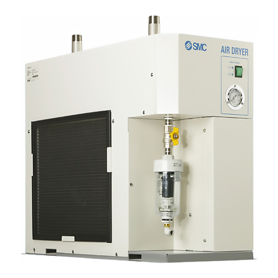
Refrigerated Air Dryer
This manual is intended to explain the installation and operation of the product. Only
those who have thorough understanding of the fundamental operating procedure or
have basic knowledge and skills of handling industrial products are qualified to perform
installation and operation.
Please read this manual prior of using the air dryer.
PRODUCT NAME
MODEL / Series
IDFC60-23-C,L,R,T,V
IDFC70-23-C,L,R,T,V
IDFC80-23-C,L,R,T,V
IDFC90-23-C,L,R,T,V
Keep the manual readily available for reference.
IDX-OM-U010
Advertisement
Table of Contents

Related Manuals for SMC Networks IDFC60 Series


Summary of Contents for SMC Networks IDFC60 Series
- Page 1 IDX-OM-U010 PRODUCT NAME Refrigerated Air Dryer MODEL / Series IDFC60-23-C,L,R,T,V IDFC70-23-C,L,R,T,V IDFC80-23-C,L,R,T,V IDFC90-23-C,L,R,T,V This manual is intended to explain the installation and operation of the product. Only those who have thorough understanding of the fundamental operating procedure or have basic knowledge and skills of handling industrial products are qualified to perform installation and operation.
- Page 2 Foreword Thank you for purchasing SMC’s refrigerated air dryer (hereinafter referred to as the “product”). For safety and long life of the product, be sure to read this Operation Manual (hereinafter referred to as the “manual”) and clearly understand the contents. ●...
-
Page 3: Table Of Contents
IDX-OM-U010 Contents Contents Chapter 1 Safety Instructions ............1-1 ..................1-1 EFORE SING RYER 1.1.1 Danger, Warning and Caution ..................... 1-1 ..........1-2 AZARD CLASSIFICATIONS AZARD ARNING ABELS 1.2.1 Hazard of Electricity ......................1-2 1.2.2 Hazard of Hot Surface ......................1-2 1.2.3 Danger of Compressed Air Circuit .................. - Page 4 IDX-OM-U010 Contents Chapter 7 Documents ............... 7-1 ......................7-1 PECIFICATIONS ................... 7-2 EFRIGERANT AND VALUE ........................ 7-3 IMENSIONS ....................... 7-4 LECTRIC CIRCUIT ..................7-5 EFRIGERANT IRCUIT Chapter 8 Option C ................8-1 ......................8-1 PECIFICATIONS ............8-1 RECAUTIONS FOR INSTALLATION AND HANDLING Chapter 9 Option L ................
-
Page 5: Chapter 1 Safety Instructions
IDX-OM-U010 Chapter 1 Safety Instructions Chapter 1 Safety Instructions Before using the product, be sure to read and understand all the important actions highlighted in this manual. 1.1 Before Using Air Dryer. This chapter is intended to specifically describe the safety related issues for handling the product. Read this before handling the product. -
Page 6: Hazard Classifications/ Hazard Warning Labels
IDX-OM-U010 Chapter 1 Safety Instructions 1.2 Hazard classifications/ Hazard Warning Labels To ensure the safety of the operators, potential hazards are classified and marked with warning labels. Confirm the potential hazards and positions of the labels before operation. WARNING - Transportation, installation, and maintenance involve risks and should only be carried out by people who have sufficient knowledge and experience about the product and its incidental device. -
Page 7: Positions Of Hazard Warning Labels
IDX-OM-U010 Chapter 1 Safety Instructions 1.2.4 Positions of Hazard Warning labels WARNING - Confirm the positions of the hazard warning labels. Front Hazard classifications/ Hazard Warning Labels IDFC60/70/80/90 Series... -
Page 8: Product Label
IDX-OM-U010 Chapter 1 Safety Instructions 1.2.5 Product label ● Product number (SERIAL No.) ● Refrigerant type and amount * Example: IDFC60-23. Front Structure of the product number W R 0001 (2018 April) 0001 Year Symbol Note Month Symbol Note Serial No. 2018 Repeated from A to Z Repeated from A to Z... -
Page 9: Waste Disposal
IDX-OM-U010 Chapter 1 Safety Instructions 1.3 Waste Disposal When you dispose of the product, you should collect the refrigerant and the refrigerant oil enclosed in the refrigerant circuit. CAUTION - This product uses Fluorocarbon (HFC) as a refrigerant. - This product is specified by “Class 1 Act on Rational Use and Proper Management of Fluorocarbons JAPAN.”... -
Page 10: Limited Warranty And Disclaimer/ Compliance Requirements
IDX-OM-U010 Chapter 1 Safety Instructions 1.4 Limited Warranty and Disclaimer/ Compliance Requirements The product used is subject to the following “Limited warranty and Disclaimer” and “Compliance Requirements”. Read and accept them before using the product. Limited Warranty and Disclaimer 1. The warranty period of the product is 1 year in service or 1.5 years after the product is delivered. -
Page 11: Chapter 2 Name And Function Of Parts
IDX-OM-U010 Chapter 2 Name and Function of Parts Chapter 2 Name and Function of Parts 2.1 Name and Function of Parts Right ventilation grille (air discharge opening) Hot air is exhausted from the fan motor. Do not block the grill. Compressed air inlet (IN) Compressed air outlet (OUT) Switch with lamp... - Page 12 IDX-OM-U010 Chapter 2 Name and Function of Parts Left ventilation grille (air intake opening) (Dustproof filter) Air intake for cooling. Do not block vents. Name and Function of Parts IDFC60/70/80/90 Series...
-
Page 13: Chapter 3 Transportation And Installation
IDX-OM-U010 Chapter 3 Transportation and installation Chapter 3 Transportation and installation WARNING Use the product in an appropriate manner, and pay attention to safety, particularly physical safety of operators, during the installation, operation, maintenance and checks of the product. CAUTION Tranportation, installation, and maintenance including dangerous work must be done by personnel who have require knowledge and experience about the product and system. -
Page 14: Installation
IDX-OM-U010 Chapter 3 Transportation and installation 3.2 Installation 3.2.1 Environment Do not use in the following environments, as it may lead to a breakdown. Potential malfunction or damage to the product may occur if these instructions are disregarded. - Avoid locations where the air dryer will be in direct contact with wind or rain. (Avoid locations where relative humidity is 85% or more) - Avoid locations where water, water vapor, salt water, or oil may splash on the product. -
Page 15: Air Piping
IDX-OM-U010 Chapter 3 Transportation and installation 3.2.3 Air piping Connection of the inlet and outlet of compressed air should be made removable by using union and so on. When an air fitting is connected with the body of the product, hold the pneumatic piping at the body with a pipe wrench and tighten. -
Page 16: Drain Tube
IDX-OM-U010 Chapter 3 Transportation and installation 3.2.4 Drain tube - A drain tube of 12mm O.D. is included as an accessory. The outlet end of the tube is released to atmosphere and lets the drain flow through the tube. (When customers prepare the drain tube, keep its length at 5m or less and the I.D. at 8mm or larger for correct operation of the auto drain) - Using the pressure of the compressed air, the drain will be discharged periodically. -
Page 17: Electrical Wiring
IDX-OM-U010 Chapter 3 Transportation and installation 3.2.5 Electrical wiring WARNING - Only qualified personnel should do electrical wiring work. - Cut off the power supply for safety before the wiring. Wiring with the product energized is strictly prohibited. - Use a power supply suitable for the specifications of the product. - Supply power from a stable place, which is free from the effects of any surge. - Page 18 IDX-OM-U010 Chapter 3 Transportation and installation Wiring procedure (1) Remove the front panel. (2) Pass the cable through the strain relief to connect to the terminal block. (refer to the label on the terminal block) M3.5 Screw tightening torque : 1.0 to 1.3N・m M4.0 Screw tightening torque : 1.4 to 2.0N・m Do not touch any equipment other than the terminal block during wiring.
-
Page 19: Cautions About Reinstallation
IDX-OM-U010 Chapter 3 Transportation and installation 3.3 Cautions about Reinstallation CAUTION Only someone who has enough knowledge about the product and incidental devices should reinstall it in another place. If you move the product and reinstall it into another place after some operations (including trial running), all installation instructions in chapter 2 should be followed as well as the following instructions. - Page 20 IDX-OM-U010 Chapter 3 Transportation and installation Cautions about Reinstallation IDFC60/70/80/90 Series...
-
Page 21: Chapter 4 Operation/ Shutdown
IDX-OM-U010 Chapter 4 Operation/ Shutdown Chapter 4 Operation/ Shutdown CAUTION Only someone who has enough knowledge and experience about the product and incidental devices should operate or shut down the product. 4.1 Check points before operation Before trial operation, check following points. Installation state ... -
Page 22: Stop
IDX-OM-U010 Chapter 4 Operation/ Shutdown 4.3 Stop 1) Turn off the switch with lamp. 2) The lamp turns off and operation stops. 4.4 Cautions for re-start Allow at least 3 minutes before restarting the product. If the product is restarted within 3 minutes after being stopped, the protection circuit will be activated, and the dryer will not start. -
Page 23: Chapter 5 Checks And Maintenance
IDX-OM-U010 Chapter 5 Checks and Maintenance Chapter 5 Checks and Maintenance WARNING - Only people who have sufficient knowledge and experience about the product and its incidental devices are allowed to perform maintenance. - Before maintenance, read and understand the important cautionary notifications in this operation manual. -
Page 24: Regular Maintenance
IDX-OM-U010 Chapter 5 Checks and Maintenance 5.2 Regular maintenance 5.2.1 Clean the dustproof filter of the ventilation grille Vacuum or air-blow the filter every month to remove dust and particles of the ventilation grille. CAUTION Wear protective goggles or mask during air blow. 5.2.2 Auto drain maintenance Remove the dust accumulated in the auto drain element and bowl assembly every month. - Page 25 IDX-OM-U010 Chapter 5 Checks and Maintenance 7) Pull down the lock button of the bowl assembly with your thumb, and rotate the bowl assembly anticlockwise by 30 degrees to align the marks. 8) Remove the bowl assembly by pulling down on it. Mark Bowl assembly Lock...
- Page 26 IDX-OM-U010 Chapter 5 Checks and Maintenance Regular maintenance IDFC60/70/80/90 Series...
-
Page 27: Chapter 6 Troubleshooting
IDX-OM-U010 Chapter 6 Troubleshooting Chapter 6 Troubleshooting 6.1 Troubleshooting Refer to the table below if any abnormality is found. If there is something that is not clear, please turn off the power supply and contact our service office. Problems Possible causes Action Air dryer does not Power cord is loose or not... - Page 28 IDX-OM-U010 Chapter 6 Troubleshooting Problem Possible causes Action The refrigerant Poor ventilation in installation - Keep the ambient temperature low by ventilation. pressure gauge location. indicates red zone. Ambient temperature is too high. Ventilation grille is obstructed by a - Install so that the ventilation grill are 600mm or more wall or blocked with dust.
- Page 29 IDX-OM-U010 Chapter 6 Troubleshooting Problem Possible causes Countermeasures Air leakage Air leaks out from the O-ring of the bowl is damaged. - Replace the bowl O-ring with a from the auto gap between the bowl new one. When assembling the drain and body.
-
Page 30: Reset The Thermal Relay And High Pressure Switch
IDX-OM-U010 Chapter 6 Troubleshooting 6.2 Reset the Thermal relay and High Pressure Switch When the lamp goes off and the compressor for refrigeration stops during operation, the thermal relay or high voltage pressure switch has activated to protect the compressor for refrigeration. It is necessary to reset it manually. -
Page 31: Chapter 7 Documents
IDX-OM-U010 Chapter 7 Documents Chapter 7 Documents 7.1 Specifications Model IDFC60-23 IDFC70-23 IDFC80-23 IDFC90-23 Specifications Fluid Compressed Air Inlet air temperature 20 to 65 (Note7) Inlet air pressure 0.15 to 1.0MPa Ambient temperature (Humidity) 20 to 45 C (Relative humidity 85% or less) At outlet pressure 4.7m /min... -
Page 32: Refrigerant And Gwp Value
IDX-OM-U010 Chapter 7 Documents Note 5: Products other than Option R are not equipped with an earth leakage breaker. Purchase an appropriate earth leakage breaker separately. Use an earth leakage breaker with a leak current sensitivity of 30mA. Note 6: This is the value specified by IPCC4 AR4. The value specified by“Class 1 Act on Rational Use and Proper Management of Fluorocarbons JAPAN.”... -
Page 33: Dimensions
IDX-OM-U010 Chapter 7 Documents 7.3 Dimensions Compressed air inlet Compressed air outlet Port size Port size Unit: mm Unit: mm Model Port Size IDFC60 12.5 IDFC70 R1-1/2 IDFC80 11.0 IDFC90 (Hole diameter:Ø13) Anchor bolt location Unit: mm IDFC80 IDFC60 IDFC90 (957) エアドライヤ外寸... -
Page 34: Electric Circuit
IDX-OM-U010 Chapter 7 Documents 7.4 Electric circuit ■IDFC60/70 230VAC 1PH 50Hz SYMBOL DESCRIPTION Refrigerating compressor Overload relay Fan motor Magnetic contactor High pressure switch Switch with lamp Thermal relay Capacitor for refrigerating compressor Capacitor for fan motor Terminal block Connector GFCI Ground fault circuit interrupter Electronic drain valve... -
Page 35: Air/ Refrigerant Circuit
IDX-OM-U010 Chapter 7 Documents 7.5 Air/ Refrigerant Circuit Compressored Compressored air outlet air inlet Cooler re-heater (Heat exchanger) Ball valve Auto drain Capillary tube High pressure switch Volume Condenser control valve Drain outlet Refrigerant Fan motor pressure gauge Accumulator Compressor for refrigeration Air circuit The humid hot air that enters the air dryer first goes into the reheater, and exchanges its heat with... - Page 36 IDX-OM-U010 Chapter 7 Documents Air/ Refrigerant Circuit IDFC60/70/80/90 Series...
-
Page 37: Chapter 8 Option C
IDX-OM-U010 Chapter 8 Option C Chapter 8 Option C 8.1 Specifications Special epoxy resin is coated on the copper tube surface to improve the corrosion resistance the special epoxy resin is only applied where the copper tubes are not protected or insulated 8.2 Precautions for installation and handling The epoxy resin minimizes the corrosion of the coated copper tubes against corrosive gas. - Page 38 IDX-OM-U010 Chapter 8 Option C Precautions for installation and handling IDFC60/70/80/90 Series...
-
Page 39: Chapter 9 Option L
IDX-OM-U010 Chapter 9 Option L Chapter 9 Option L Option L: Dryer with heavy duty auto drain. The heavy duty auto drain to be assembled by customer. 9.1 Safety instructions for use Refer to the instructions below when handling the product. WARNING - Before replacing the auto drain on the compressed air side confirm that the pressure gauge indicates zero. -
Page 40: Mount The Heavy Duty Auto Drain
IDX-OM-U010 Chapter 9 Option L 9.3 Mount the Heavy Duty Auto Drain 1) Hold the hexagonal part (width across flats: 25) at the connection port (ball valve Rc1/2) of the product with a spanner and screw-in the barrel nipple and elbow in order. 2) Screw-in the long nipple and heavy duty auto drain (width across flats of drain inlet port: 30) completely. -
Page 41: Chapter 10 Option R
IDX-OM-U010 Chapter 10 Option R Chapter 10 Option R Option R is equipped with an earth leakage breaker (GFCI). This is to shut off the power supply when over current or leakage current is applied to the air dryer. 10.1 Safety instructions for use Refer to the instructions below when handling the product. -
Page 42: Connection Of Power Supply
IDX-OM-U010 Chapter 10 Option R 10.3 Connection of power supply Connect the power cable according to the procedure below. 1) Remove the front panels. 2) Introduce the cable through the strain relief to connect to the terminal block. (refer to the label on the terminal block) M3.5 Screw tightening torque : 1.0 to 1.3N・m M4.0 Screw tightening torque : 1.4 to 2.0N・m... -
Page 43: Chapter 11 Option T
IDX-OM-U010 Chapter 11 Option T Chapter 11 Option T Option T has terminal block for the output of operation and error signals and remote control. 11.1 Safety instructions for use Refer to the instructions below when handling the product. WARNING All electrical work must be carried out in a safe manner by a qualified person in compliance with applicable national regulations. -
Page 44: Remote Operation
IDX-OM-U010 Chapter 11 Option T 11.3 Remote operation 230 VAC is applied to the terminal for remote operation. Select the appropriate switch. - For remote operation, customer operates the switch which is connected by customer with the switch with lamp ON. - Position holding switch (alternate type switch). -
Page 45: Connect The Power Cable And Signal Cable
IDX-OM-U010 Chapter 11 Option T 11.4 Connect the power cable and signal cable Connect the power cable and signal cable according to the procedure below. 1) Remove the front panel. 2) Insert the power cable to the power cable entry and connect to the terminal block. 3) Insert the signal cable to the signal cable entry and connect to the terminal block. -
Page 46: Electric Circuit
IDX-OM-U010 Chapter 11 Option T 11.5 Electric circuit ■IDFC60/70-23-T SYMBOL DESCRIPTION Refrigerating compressor Overload relay Fan motor Magnetic contactor Magnetic contactor for remote switch High pressure switch Switch with lamp Thermal relay Capacitor for refrigerating compressor Capacitor for fan motor Terminal block Connector Time delay relay... -
Page 47: Chapter 12 Option V
IDX-OM-U010 Chapter 12 Option V Chapter 12 Option V Option V is a dryer with a timer controlled solenoid valve type auto drain. The timer is adjusted by customer according to the operating conditions. 12.1 Safety instructions for use Refer to the instructions below when handling the product. WARNING - Before replacing the auto drain on the compressed air side confirm that the pressure gauge indicates zero ”. -
Page 48: Maintenance
IDX-OM-U010 Chapter 12 Option V 12.3 Maintenance Be sure to perform regular maintenance of the strainer. Follow the following steps to perform maintenance. 1) Close the ball valve. 2) Press the test switch to release the residual pressure. 3) Remove the strainer and clean it. 4) Mount the strainer and open the ball valve. -
Page 49: Chapter 13 Inspection Record
IDX-OM-U010 Chapter 13 Inspection record Chapter 13 Inspection record 13.1 Inspection record We recommend keeping the inspection record for maintenance or service. Product No. Description Contents of check Date IDFC60/70/80/90 Series 13.1 Inspection record 13-1... - Page 52 Revision Rev G:Oct,2019 4-14-1, Sotokanda, Chiyoda-ku, Tokyo 101-0021 JAPAN Tel: + 81 3 5207 8249 Fax: +81 3 5298 5362 URL http://www.smcworld.com Note: Specifications are subject to change without prior notice and any obligation on the part of the manufacturer. ©...
Need help?
Do you have a question about the IDFC60 Series and is the answer not in the manual?
Questions and answers