Table of Contents
Advertisement
Quick Links
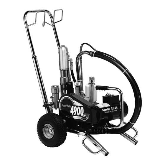
PowrTwin 4900
PowrTwin 4900
Model Number:
Gas Bare
DC Electric Bare
Gas Complete
Gas/Electric Complete
Printed in the U. S. A.
335-305
335-310
335-315
335-320
Owner's Manual
For professional use only
Do not use this equipment
before reading this manual!
NOTE: This manual contains important warnings
and instructions. Please read and retain for
reference.
0205 © 2005 Titan Tool Inc. All rights reserved. Form No. 313-2482A
XLT
XLT
Advertisement
Table of Contents

Related Manuals for Titan Tool Speeflo PowrTwin 4900XLT


Summary of Contents for Titan Tool Speeflo PowrTwin 4900XLT
- Page 1 DC Electric Bare 335-310 NOTE: This manual contains important warnings Gas Complete 335-315 and instructions. Please read and retain for Gas/Electric Complete 335-320 reference. 0205 © 2005 Titan Tool Inc. All rights reserved. Form No. 313-2482A Printed in the U. S. A.
-
Page 2: Table Of Contents
• The equipment and objects in and around the spray area must be properly grounded to prevent static sparks. • Use only conductive or grounded high pressure fluid hose. Gun must be grounded through hose connections. © Titan Tool Inc. All rights reserved. -
Page 3: Grounding Instructions
Never repair a paint hose. Replace it with another grounded high-pressure hose. • Do not spray outdoors on windy days. • Wear clothing to keep paint off skin and hair. © Titan Tool Inc. All rights reserved. -
Page 4: Gasoline Engine Safety
313-1837 carbon steel, stainless steel, tungsten carbide, , thiokol labels, order directly from impregnated leather, ultra high molecular weight polyethylene. 313-1306 Spanish Speeflo free of charge. 313-1307 313-785 French 313-786 313-787 German 313-788 © Titan Tool Inc. All rights reserved. -
Page 5: Introduction
If you notice any undesirable operating characteristics while using a gasoline that contains alcohol, or one that you think contains alcohol, switch to a gasoline that you know does not contain alcohol. © Titan Tool Inc. All rights reserved. -
Page 6: Operation
Use of Speeflo's Coolflo™ Hydraulic Fluid (P/N 430-361) is mandatory in the hydraulic system. Do not use any other hydraulic fluid. Use of any other hydraulic fluid may seriously damage the hydraulic system and will void the warranty. © Titan Tool Inc. All rights reserved. -
Page 7: Preparing To Paint
• turn the engine switch to the OFF position. b. To turn off the electric motor, • set the pressure to minimum by turning the pressure control knob fully counterclockwise, • move the ON/OFF switch to the OFF position. © Titan Tool Inc. All rights reserved. -
Page 8: Painting
• turn the engine switch to the ON position, and • pull the starter rope briskly until the engine starts. © Titan Tool Inc. All rights reserved. -
Page 9: Pressure Relief Procedure
1. Follow the “Pressure Relief Procedure” found in the Operation section of this manual. 2. Remove the gun tip and tip guard and clean with a brush using the appropriate solvent. © Titan Tool Inc. All rights reserved. -
Page 10: Cleaning A Clogged Tip
5. Place the thin PTFE gasket onto the step at the top of the filter body. 6. Place the thick PTFE gasket onto the top of the thin gasket. 7. Tighten the filter cap assembly onto the filter body. © Titan Tool Inc. All rights reserved. -
Page 11: Maintaining The Hydraulic System
(one should not be faster than the other). A fast up or limited to the original manufacturer. down stroke may indicate air in the system or malfunctioning valve or seats (see the Troubleshooting section). © Titan Tool Inc. All rights reserved. -
Page 12: Replacing The Motor Brushes (Electric Motor)
Brush Holder Spring Spring Clip 6. Place the spring on the brush as shown above. Push in and hook the spring clip. Repeat this procedure for the other side. 7. Reinstall both inspection covers. © Titan Tool Inc. All rights reserved. -
Page 13: Troubleshooting
4. Increase hose size to minimize pressure long drop through hose and/or reduce hose length. Pump chatters on up or down 1. Solvent has caused upper packing to 1. Replace packing. stroke swell © Titan Tool Inc. All rights reserved. -
Page 14: Hydraulic Motor
NOTE: Engine labors at stall This will help determine if center o-ring is on both strokes. blown on spool valve. If hot, remove and replace o-ring. 2. Replace hydraulic pump. © Titan Tool Inc. All rights reserved. -
Page 15: Spray Patterns
Remove restrictions in system; clean tip screen if filter is used. Round pattern 1. Worn tip 1. Replace tip. 2. Fluid too heavy for tip 2. Increase pressure. Thin material. Change nozzle tip. © Titan Tool Inc. All rights reserved. - Page 16 • Portez un masque de protection. • Portez des vêtements de protection, selon les instructions du fabricant de peinture. © Titan Tool Inc. Tous droits réservés. Français...
- Page 17 être utilisée à l'extérieur, le suffixe W-A doit apparaître après la désignation du type de câble. Par exemple, la désignation SJTW-A indiquerait que le câble peut être utilisé à l'extérieur. © Titan Tool Inc. Tous droits réservés. Français...
- Page 18 • Use ropa de protección, según lo requiera el fabricante del algunos revestimientos que se inyectan directamente en la producto. corriente sanguínea. Es recomendable consultar a un cirujano plástico o reconstructor de manos. © Titan Tool Inc. Todos los derechos reservados. Español...
- Page 19 AWG. Si se va a utilizar un cable de extensión en el exterior, debe estar marcado con el sufijo A-W después de la designación del tipo de cable. Por ejemplo, SJTW-A para indicar que el cable es apropiado para su uso en exteriores. © Titan Tool Inc. Todos los derechos reservados. Español...
-
Page 20: Parts Lists And Service Instructions
(For use with older hose assemblies that have 1/8” NPT thread — allows the attachment of the older hose to bleed valve P/N 944-030.) 944-040 Bleed valve kit (includes items 1, 2, 4 and bushing P/N 191-211) © Titan Tool Inc. All rights reserved. -
Page 21: Cart Assembly
Roll pin .............2 862-411 Locknut.............1 Belt Guard Assembly Item Part # Description Quantity 448-233 Belt guard ..........1 862-002 Lock washer ..........1 862-411 Nut............1 862-001 Washer .............1 862-436 Screw ............1 313-2489 Label (not shown)........1 © Titan Tool Inc. All rights reserved. -
Page 22: Dc- Electric Convertokit
506-257 Circuit breaker reset.........1 506-258 Fan (not shown) ........1 506-260 ON/OFF switch.........1 424-285 Belt, "V" 978-350 Motor, (not shown, not part of assembly) DC-Electric, 2 HP, 50 / 60 Hz, 115 V ..1 © Titan Tool Inc. All rights reserved. -
Page 23: Gas Convertokit
860-004 Flat washer..........8 980-332 Engine, gas 4.0 HP, Honda ......1 980-307 Key ............1 448-221 Pulley............1 448-336 Mounting plate, gas eng......1 860-502 Stop nut ............4 424-285 Belt, "V" (not shown, not part of assembly) © Titan Tool Inc. All rights reserved. -
Page 24: Bleed Valve Assembly
Outlet Ports ........(1) 1/4" NPT(F) for bleed valve (1) 3/8" NPT(F) with 1/4 NPSM(M) hose connection (1) 3/8" NPT(F) plugged for additional gun hookup Wetted Parts ........Carbon steel with electroless nickel and cadmium plating, stainless steel, tungsten carbide, PTFE © Titan Tool Inc. All rights reserved. -
Page 25: Hydraulic System
Use hydraulic sealant Use hydraulic sealant Use hydraulic sealant Torque to 15 FT/LBS (20,5 N/m) Torque to 15 FT/LBS (20,5 N/m) Torque to 20 FT/LBS (28 N/m) Torque to 15 FT/LBS (20,5 N/m) © Titan Tool Inc. All rights reserved. -
Page 26: Hydraulic Motor
431-019 O-ring kit...........1 pump. 700-499 O-ring ............2 2. Remove the two mounting screws and two lock washers (17 and 16 in Cart Assembly parts list) that attach the motor/pump assembly to the cart. © Titan Tool Inc. All rights reserved. - Page 27 O-Rings of the hydraulic motor. 2. Install o-rings (2) on trip retainers (1). Install trip retainer balls (4) followed by springs (3) which, when installed, will hold spool/sleeve set (5) in proper place for assembly. © Titan Tool Inc. All rights reserved.
-
Page 28: Fluid Section
Fluid section service kit, minor (includes items 1, 3, 4, 10, 12, 15, 17, 19, and Loctite P/N 426-051) 107-015 Foot valve assembly (includes items 16–20) 107-016 Outlet valve assembly (includes items 10–13) © Titan Tool Inc. All rights reserved. - Page 29 Loctite #242. Make sure the Loctite is only on the threads. 8. Place the lower packing spring (9) onto the outlet valve housing (13) followed by the sleeve (8) and spring retainer (7). © Titan Tool Inc. All rights reserved.
-
Page 30: Gun Manifold Assemblies (Optional)
1/4" 3/8" 3/8" 3/8" 975-111 1 Gun Add-On, 1/4"....1 .......1 .......1 975-311 1 Gun Add-On, 3/8" ....................1 .....1 ......1 975-200 Add-A-Gun Kit, 1/4" ....1 .......2 .......3 975-300 Add-A-Gun Kit, 3/8" ....................1 .....2 ......3 © Titan Tool Inc. All rights reserved. -
Page 31: Sae O-Ring Fitting Installation
Other fittings, as the ones which attach to the hydraulic pump, assemble the same but may not have the indicator.) Bent washer allows for o-ring extrusion Avoid leaving fitting too far out. O-ring cut on thread © Titan Tool Inc. All rights reserved. -
Page 32: Limited Warranty
Limited Warranty Titan Tool, Inc., (“Titan”) warrants that at the time of delivery to the original purchaser for use (“End User”), the equipment covered by this warranty is free from defects in material and workmanship. With the exception of any special, limited, or extended warranty published by Titan, Titan’s obligation under this warranty is limited to replacing or repairing without charge those parts...
Need help?
Do you have a question about the Speeflo PowrTwin 4900XLT and is the answer not in the manual?
Questions and answers