Table of Contents
Advertisement
Quick Links
Advertisement
Table of Contents

Subscribe to Our Youtube Channel
Related Manuals for Greenlee 5990A-C


Summary of Contents for Greenlee 5990A-C
- Page 1 INSTRUCTION MANUAL INSTRUCTION MANUAL 5990A Megohmmeter Read and understand all of the instructions and safety information in this manual before operating or servicing this tool. 52084986 © 2018 Greenlee Tools, Inc. 8/18 1.888.610.7664 www.calcert.com sales@calcert.com...
-
Page 2: Table Of Contents
Table of Contents Description ....................3 Safety ...................... 3 Purpose....................3 Important Safety Information............... 4–6 Identification ..................7-11 LC Display ..................7 Operator’s Panel ................8 Connectors .................. 9–10 High Voltage Shielded Test Tips with High Voltage Alligator Clips ... 11 Performing Measurements .............. -
Page 3: Description
Greenlee Tools, Inc. Do not discard this product or throw away! All specifications are nominal and may change as design improvements occur. Greenlee Tools, Inc. shall not be liable for damages resulting from misapplication or misuse of its products. -
Page 4: Important Safety Information
Important Safety Information SAFETY ALERT SYMBOL This symbol is used to call your attention to hazards or unsafe practices which could result in an injury or property damage. The signal word, defined below, indicates the severity of the hazard. The message after the signal word provides information for preventing or avoiding the hazard. - Page 5 5990A Important Safety Information Electric shock and fire hazard: • Do not expose this unit to rain or moisture. • Do not use the unit if it is wet or damaged. • Use test leads or accessories that are appropriate for the application. See the category and voltage rating of the test lead or accessory.
- Page 6 Important Safety Information Electric shock hazard: • Do not attempt to repair this unit. It contains no user-serviceable parts. • Do not expose the unit to extremes in temperature or high humidity. See Specifications. Failure to observe these precautions may result in injury and can damage the unit. Working with the instrument: •...
-
Page 7: Identification
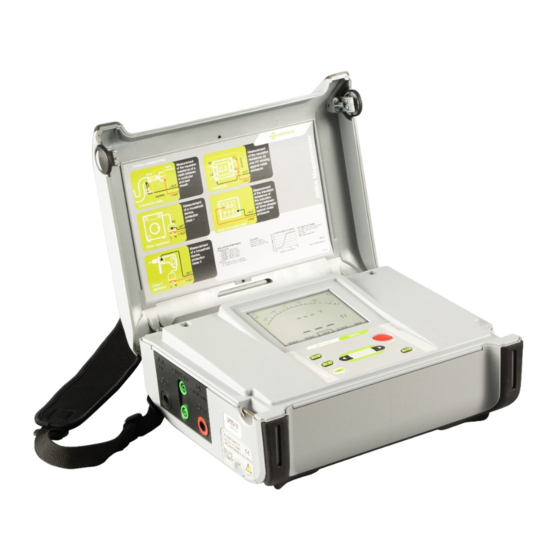
5990A Instrument Description Instrument Casing The instrument is housed in a plastic box that maintains the protection class defined in the general specifications. The LCD has a backlight and offers easy-to-read results. See Fig.1 below. Fig. 1 LCD Display Legend: 1.. -
Page 8: Operator's Panel
Instrument Description (cont’d) Operator’s Panel The operator’s panel is shown in Fig. 2 below. 5990A Keypad Fig. 2. Front Panel Legend: 1...Ω: Press to switch to Insulation Measurement Mode. Press again to set a resistance limit value. 2..V: Press to switch to Voltage measurement mode. 3.. -
Page 9: Connectors
5990A Instrument Description (cont’d) Connectors The 5990A Tester contains the following connections: • Four banana safety sockets for test leads (Fig. 3). • Socket for mains supply cable (Fig. 4). Fig. 3 Test Leads Connector Diagram 1..(-OUT): Negative Insulation Resistance test terminal 2.. - Page 10 Instrument Description (cont’d) Connectors (cont’d) Fig. 4. Mains connector Fig. 4 Mains Connector 1..Mains connector: This is to connect the instrument to the mains supply. Use original mains supply cable only! 1.888.610.7664 www.calcert.com sales@calcert.com...
-
Page 11: High Voltage Shielded Test Tips With High Voltage Alligator Clips
5990A Instrument Description (cont’d) High Voltage Shielded Test Tips with High Voltage Alligators Clips Application notes: These test leads are designed for diagnostic testing of insulation and hand held testing of insulation. Insulation ratings: • High voltage banana connector (red, black): 5kV d.c Fig.5 (double insulation). -
Page 12: Performing Measurements
Performing Measurements Switching On the Instrument Auto-Calibration The instrument is switched ON by pressing the ON/OFF key. After turning on (Fig. 7), the instrument executes the auto-calibration (Fig. 8). Note: If batteries are defective or missing and the instrument is powered from mains supply, the instrument cannot be turned ON. - Page 13 5990A Performing Measurements (cont’d) Note: If the instrument detects a faulty state during the auto-calibration, the fail icon (X) will be displayed: A common reason for failure is improper environmental conditions. This includes excessive hu- midity or excessive temperature. In this case it is possible to perform measurements by pressing the START/STOP button again but results could be outside of the technical specification.
-
Page 14: Measurements
Measurements General Information about DC High voltage testing The purpose of insulation tests Insulating materials are important parts of almost every electrical product. The material’s proper- ties depend not only on its compound characteristics but also on temperature, pollution, mois- ture, aging, electrical and mechanical stress, etc. -
Page 15: Guard Terminal
5990A Measurements (cont’d) Guard terminal The purpose of the GUARD terminal is to lead away potential leakage currents (e.g. surface currents), which are not a result of the measured insulation material itself but are a result of surface contamination and moisture. This current interferes with the Insulation Resistance Measurement. -
Page 16: Insulation Resistance Measurement
Measurements (cont’d) Insulation Resistance measurement Select this function by pressing the Ω button. It will display the following states (Initial Display and Display with results). See Fig. 12 below. Initial display Display with results Fig. 12 Insulation Resistance Function Display States Legend of displayed symbols in Fig 12: Insulation Resistance Name of selected function... - Page 17 5990A Measurements (cont’d) Set-up test voltage for Insulation Resistance (Fig.13): Adjust test voltage using the t and u buttons. Legend of displayed symbols: Name of selected function Insulation Resistance Selected test voltage Nominal 250V Fig. 13 Set-Up Test Voltage in Insulation Resistance Measurement Set-Up Insulation Resistance Limit Value for Insulation Resistance (Fig.13):...
-
Page 18: Voltage Measurement
Measurements (cont’d) Voltage Measurement Select this function by pressing the V button. Voltage measurement is active immediately after entering the function. See Fig. 14 below. Fig. 14 Voltage Function Display Measurement Procedure: • Connect the test leads to the instrument and to the measured source. •... -
Page 19: Maintenance
To maintain the operator’s safety and to ensure the reliability of the instrument it is advisable to inspect the instrument on a regular basis. Check that the instrument and its accessories are not damaged. If any defect is found please consult the Greenlee Service Center at 800-435-0786. Insertion and Charging Batteries for the First Time Battery cells are stored in the bottom section of the instrument casing under the battery cover (see Fig. - Page 20 Maintenance (cont’d) If the batteries have been stored for a long time, it normally takes about 3 charge and discharge cycles for the batteries to regain full capacity. Battery cells are stored in the bottom section of the instrument under the battery cover (see Fig.
- Page 21 • Do not use petrol or hydrocarbon based liquids. • Do not spill cleaning liquid on the instrument. Calibration Greenlee recommends that the 5990A Megohmmeter be routinely calibrated to ensure accuracy. Service For repairing under or out of warranty period contact your distributor for further information.
-
Page 22: Specifications
Specifications Accuracy Accuracy is specified from -20°C to 40°C Measurements Note: All data regarding accuracy is given for nominal (reference) environment condition. Insulation Resistance Nominal test voltage: 250 V, 500 V, 1 kV, 2.5 kV, 5 kV Current capability of test generator: >1 mA Short-circuit test current: 5 mA. -
Page 23: General Capability Vs Resistance
5990A Specifications (cont’d) Generator Capability vs Resistance Utest=5kV Voltage Voltage AC or DC Display range test voltage (V) Resolution Accuracy 0 - 600 ± (3 % of reading + 4 V) Frequency of External Voltage Display range test voltage (V) Resolution Accuracy 0 and 45 - 65... -
Page 24: General Specifications
General Specifications Battery Power Supply..............7.2 V DC (6 × 1.2 V NiMHC size) Mains Power Supply..............90-260 V AC, 45-65 Hz, 40 VA Over-Voltage Category..............300 V CAT III Protection Classification.............Double Insulation Measurement Category..............600 V CAT IV Pollution Degree.................2 Degree of Protection..............IP 40 with case closed Dimensions (w ×... -
Page 25: Measurement Categories
Primary supply level. Overhead lines and other cable systems. Some examples include cables, meters, transformers, and other exterior equipment owned by the power utility. Statement of Conformity Greenlee Tools, Inc. is certified in accordance with ISO 9000 (2000) for our Quality Management Systems. 1.888.610.7664 www.calcert.com...
Need help?
Do you have a question about the 5990A-C and is the answer not in the manual?
Questions and answers