Table of Contents
Advertisement
Quick Links
The information contained in this document supersedes all similar information that
may be found elsewhere in this manual.
Service – Due to the sophisticated
nature of the sensors and associated
instrumentation
provided
Piezotronics, user servicing or repair is
not recommended and, if attempted,
may void the factory warranty. Routine
maintenance, such as the cleaning of
electrical connectors, housings, and
mounting surfaces with solutions and
techniques that will not harm the
physical material of construction, is
acceptable. Caution should be observed
to ensure that liquids are not permitted
to migrate into devices that are not
hermetically
sealed.
should only be wiped with a dampened
cloth and never submerged or have
liquids poured upon them.
Repair – In the event that equipment
becomes
damaged
operate, arrangements should be made
to
return
the
equipment
Piezotronics for repair. User servicing or
repair is not recommended and, if
attempted,
may
warranty.
Calibration – Routine calibration of
sensors and associated instrumentation
is recommended as this helps build
confidence in measurement accuracy
and
acquired
calibration
cycles
established by the users own quality
regimen. When in doubt about a
calibration cycle, a good "rule of thumb"
is to recalibrate on an annual basis. It is
by
PCB
Such
devices
or
ceases
to
to
PCB
void
the
factory
data.
Equipment
are
typically
Service, Repair, and Return
Policies and Instructions
also good practice to recalibrate after
exposure to any severe temperature
extreme,
shock,
environmental influence, or prior to any
critical test.
PCB Piezotronics maintains an ISO-
9001 certified metrology laboratory and
offers calibration services, which are
accredited by A2LA to ISO/IEC 17025,
with full traceability to SI through
N.I.S.T. In addition to the normally
supplied calibration, special testing is
also available, such as: sensitivity at
elevated or cryogenic temperatures,
phase response, extended high or low
frequency response, extended range,
leak
testing,
hydrostatic
testing, and others. For information on
standard
recalibration
special testing, contact your local PCB
Piezotronics
distributor,
representative,
or
service representative.
Returning
Equipment
these procedures will ensure that your
returned materials are handled in the
most
expedient
returning
any
equipment
Piezotronics,
contact
distributor,
sales
factory customer service representative
to obtain a Return Warranty, Service,
Repair, and Return Policies and
Instructions
Materials
(RMA) Number. This RMA number
should be clearly marked on the outside
of all package(s) and on the packing
load,
or
other
pressure
services
or
sales
factory
customer
–
Following
manner.
Before
to
PCB
your
local
representative,
or
Authorization
Advertisement
Table of Contents

Related Manuals for PCB Piezotronics IMI SENSORS 682 Series


Summary of Contents for PCB Piezotronics IMI SENSORS 682 Series
- Page 1 Piezotronics, user servicing or repair is critical test. not recommended and, if attempted, may void the factory warranty. Routine PCB Piezotronics maintains an ISO- maintenance, such as the cleaning of 9001 certified metrology laboratory and electrical connectors, housings, and offers calibration services, which are...
- Page 2 50% of the general contact numbers are: replacement cost returned item(s). PCB will provide a price PCB Piezotronics, Inc. quotation replacement 3425 Walden Ave. recommendation for any item whose Depew, NY14043 USA repair costs would exceed 50% of...
- Page 3 PCB工业监视和测量设备 - 中国RoHS2公布表 PCB Industrial Monitoring and Measuring Equipment - China RoHS 2 Disclosure Table 有害物质 汞 镉 六价铬 (Cr(VI)) 多溴联苯 (PBB) 多溴二苯醚 (PBDE) 部件名称 铅 (Pb) (Hg) (Cd) 住房 PCB板 电气连接器 压电晶体 环氧 铁氟龙 电子 厚膜基板 电线 电缆 塑料 焊接...
- Page 4 Component Name Hazardous Substances Lead Mercury Cadmium Chromium VI Polybrominated Polybrominated (Pb) (Hg) (Cd) Compounds Biphenyls Diphenyl (Cr(VI)) (PBB) Ethers (PBDE) Housing PCB Board Electrical Connectors Piezoelectric Crystals Epoxy Teflon Electronics Thick Film Substrate Wires Cables Plastic Solder Copper Alloy/Brass This table is prepared in accordance with the provisions of SJ/T 11364.
- Page 5 ® 682 Series 4-20mA Din Rail ICP Signal Conditioner Operating Guide with Enclosed Warranty Information 3425 Walden Avenue, Depew, New York 14043-2495 Phone (716) 684-0003 Fax (716) 684-3823 Toll Free Line 1-800-959-4IMI MANUAL NUMBER: 60419 MANUAL REVISION: ECN NUMBER: 46422...
-
Page 6: Table Of Contents
Table of Contents Introduction ........................Page 3 Block diagram ......................Page 3 General Features Page 4 ............................Installation and Wiring ..................... Page 5 Configuring the 682BX3 ....................Page 9 ESD Sensitivity ....................... Page 12 Ordering Information ...................... Page 13 Warranty/Servicing Warranty, Service &... -
Page 7: Introduction
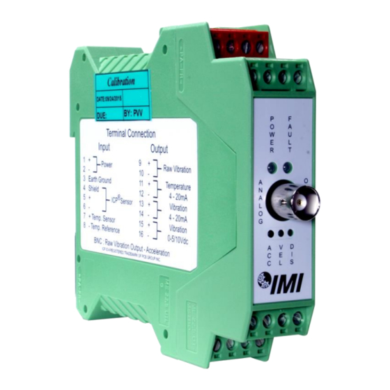
Introduction ® The 682 Series is a 4-20mA Din Rail Signal Conditioner designed to interface with IMI Sensor’s ICP Accelerometer. Acceleration, Velocity, or Displacement can be converted to a 4-20mA signal by simple DIP Switch selection internal to the Din Rail enclosure. An additional standard feature of the 682 Series is the ability to convert the temperature output from an accelerometer (when equipped) to 4-20mA. -
Page 8: General Features
General Features ® External transmitters, signal conditioners, and ICP power supplies can be eliminated by direct connection of the sensor to the Din Rail Signal Conditioner. Optional 500Vdc Input to Output Electrical Isolation. Selectable 24Vdc Unregulated, 18Vdc regulated, 4mA excitation to power sensor ... -
Page 9: Installation And Wiring
Installation and Wiring Installation The 682 Series is designed to be mounted on a 35mm Din Rail. Do not install in a harsh area where it can be exposed to cleaning fluids or machine oils. IMI Sensors recommends mounting the 682BX3 in a type NEMA 4 enclosure to protect the electronics from contamination. - Page 10 Connector and Pinout Diagram The 682 Series uses plug-in type screw terminal connectors for all input and output connections. Strip off 8mm of insulation from the connection wire ends. Using a screwdriver, remove the terminal block from the enclosure in either the up or down direction, terminate the wire in the correct location. Do not exceed a torque of 0.5Nm.
- Page 11 Pin Descriptions: DC Power – Pins 1 to 3: Pin 1 +Power Pin 2 -Power/Common Pin 3 Earth Ground ® Accelerometer – Pins 4 to 6: Pin 4 Shield ® Pin 5 + ICP Accelerometer ® Pin 6 - ICP Accelerometer Temperature Sensor –...
- Page 12 Typical Wiring Diagram 682 Series Signal 682A01 Conditioner Power Power Supply Supply Signal Conditioner PAGE 8...
-
Page 13: Configuring The 682Bx3
To Maintain Conformance, Earth Ground, Power Supply Common, and I/O Shields must be connected together. Note: If using the 682 Power Supply, mount the 682 Signal Conditioner to the left of the power supply with a recommended minimum separation distance of 4” where applicable. Configuring the 682 Series Internal PC Board Diagram The Internal PC Board Diagram shows... - Page 14 S10: 10g, 1ips, 20mils S11: 5g, 0.5ips, 10mils S12: Off = 0-5Vdc Output, On = 0-10Vdc Output Internal DIP Switch Setting ® The Internal DIP Switch of the 682 Series must be configured for the Full Scale Output of the ICP Sensor connected to it.
- Page 15 Sensor Power Jumper Configuration: (Factory Default) Note: If there is no DC bias on the input signal, this will trigger the Open/short detection which subtracts 4mA from output PAGE 11...
-
Page 16: Esd Sensitivity
Warning 2 – ESD sensitivity This equipment is designed with user safety in mind; however, the protection provided by the equipment may be impaired if the equipment is used in a manner not specified by PCB Piezotronics, Inc. Caution 1 – ESD sensitivity Cables can kill your equipment. -
Page 17: Ordering Information
ESD considerations should be made prior to performing any internal adjustments on the equipment. Any piece of electronic equipment is vulnerable to ESD when opened for adjustments. Internal adjustments should therefore be done ONLY at an ESD-safe work area. Many products have ESD protection, but the level of protection may be exceeded by extremely high voltage. -
Page 18: Warranty, Service & Return Procedure
Warranty IMI instrumentation is warranted against defective material and workmanship for 1 year unless otherwise expressly specified. Damage to instruments caused by incorrect power or misapplication, is not covered by warranty. If there are any questions regarding power, intended application, or general usage, please consult with your local sales contact or distributor. -
Page 19: Customer Service
Customer Service IMI, a division of PCB Piezotronics, guarantees Total Customer Satisfaction. If, at any time, for any reason, you are not completely satisfied with any IMI product, IMI will repair, replace, or exchange it at no charge. You may also choose, within the warranty period, to have your purchase price refunded. - Page 20 PCB Piezotronics Inc. claims proprietary rights in REVISIONS the information disclosed hereon. Neither it nor any reproduction thereof will be disclosed to others DESCRIPTION without the written consent of PCB Piezotronics Inc. DIM .44 WAS .50 45450 4.47 [113.6] .44 [11.2] .890 [22.60]...
Need help?
Do you have a question about the IMI SENSORS 682 Series and is the answer not in the manual?
Questions and answers