Table of Contents
Advertisement
Quick Links
OWNER'S MANUAL
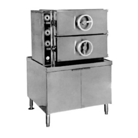
COMPARTMENT STEAMER
MODELS: GC-2S; GC-3S; GDA-2S; GHD-2S
These instructions should be read thoroughly before attempting installation. Set up,
installation and Performance Check should be performed by a qualified service
technician. The Manufacturer, Southbend (1100 Old Honeycutt Rd., Fuquay-Varina,
North Carolina 27526), informs you that unless the installation instructions for the above
described Southbend product are followed and performed by a qualified service
technician, (a person experienced in and knowledgeable concerning the installation of
commercial gas and/or electrical cooking equipment) then the terms and conditions of
the Manufacturer's Limited Warranty will be rendered void and no warranty of any kind
shall apply.
If the equipment has been changed, altered, modified or repaired by other than a
qualified service technician during or after the 12-month limited warranty period, then the
manufacturer shall not be liable for any incidental or consequential damages to any
person or to any property which may result from the use of the equipment thereafter.
Some States do not allow the exclusion or limitation of incidental or consequential
damages, so the above limitation or exclusion thereto may not apply to you.
In the event you have any question concerning the installation, use, care, or service of
the product, write Customer Service Department, Southbend Corporation, 1100 Old
Honeycutt Rd., Fuquay-Varina, North Carolina 27526.
A MIDDLEBY COMPANY
INSTALLATION
USER'S GUIDE
SERVICE
PARTS
GAS BOILER
southbend
COMPARTMENT STEAMER
GAS BOILER
(Manual Section CS)
Advertisement
Table of Contents

Related Manuals for Southbend GHD-2S


Summary of Contents for Southbend GHD-2S
- Page 1 The Manufacturer, Southbend (1100 Old Honeycutt Rd., Fuquay-Varina, North Carolina 27526), informs you that unless the installation instructions for the above described Southbend product are followed and performed by a qualified service technician, (a person experienced in and knowledgeable concerning the installation of...
-
Page 2: Table Of Contents
Congratulations! You have just purchased one of the finest pieces of heavy-duty, commercial cooking equipment on the market today. You will find that your new equipment, like all Southbend equipment, has been designed and manufactured to some of the toughest standards in the industry - those of Southbend Corporation. Each piece of Southbend equipment has been carefully engineered and designs have been verified through laboratory tests and field installations in some of the more strenuous commercial cooking applications. -
Page 3: Warranty
This warranty is subject to the following conditions: If upon inspection by Southbend or its Authorized Service Agency it is determined that this equipment has not been used in an appropriate manner, has been modified, has not been properly maintained, or has been subject to misuse or misapplication, neglect, abuse, accident, damage during transit or delivery, fire, "flood, riot or Act of God, then this warranty shall be void. - Page 4 INSTALLATION & SERVICE CONNECTIONS SECTION 1: MODELS: GC-2 & GC-3 FIG. 1 Inches 5 ½ 4 ½ LEGEND GC Supply gas through 3/4" pipe with pressure of approx. 7" W.C. For propane use 11" W.C. pressure. A gas shut off valve must be installed in supply piping convenient and adjacent to appliance. Unless otherwise specified.
- Page 5 & SERVICE CONNECTIONS INSTALLATION MODELS:GC-2, GC-3 SECTION 1: GDA-2 & GDH-2 INSTALLATION INSTRUCTIONS Cooker location should have an exhaust system provided directly above the appliance to exhaust combustion gases generated by the Gas Boiler. APPLIANCE IS INTENDED FOR USE ON NONCOMBUSTIBLF- FLOORS. MINIMUM CLEARANCE FROM COMBUSTIBLE CONSTRUCTION, 3"...
- Page 6 INSTALLATION & SERVICE CONNECTIONS SECTION 1: MODELS: GC-2 & GC-3 START UP TEST RUN Open manual gas shut off supply valve and if the appliance has a manual Blow Down Valve, close it. Open left cabinet door and turn ON power switch. Pilot light will come on (green) and water will begin to enter Boiler and required water level will be reached in about 3 minutes.
-
Page 7: Service Connections
STEAMER FUNCTIONING MODE SECTION 2: MODELS: GC-2 & GC-3 Steamers are made of two sections, the Cooker and the Cabinet. These Steamers are intended for use in commercial establishments. They are floor supported, are steam heated and incorporate steel enclosures to contain live electrical parts. Gas, Power, hot and cold water, must be supplied to these Steamers. -
Page 8: Capacities
PAN SELECTION & TIME SCHEDULES SECTION 3: MODELS: GC-2 & GC-3 COMPARTMENT CAPACITIES The Cooker compartments are provided with either removable shelf supports with slide out shelves OR universal pan supports. The following capacities for each compartment are based on full size, 12" x 20", pans and depths indicated. -
Page 9: Pan Selection
PAN SELECTION & TIME SCHEDULES SECTION 3: MODELS: GC-2 & GC-3 COOKING CHART - cont'd ITEM PAN DEPTH TIMER SETTING WEIGHT LBS NUMBER OF PANS (FULL SIZE) IN MINUTES PER PAN Carrots (sliced) 2-1/2" 18 - 21 1 - 3 Perforated 21 - 25 Corn... -
Page 10: Periodic Maintenance
PERIODIC MAINTENANCE SECTION 4: MODELS: GC-2 & 6C-3 FIG. 2 SIDE VIEW... - Page 11 PERIODIC MAINTENANCE SECTION 4: MODELS: GC-2 & GC-3 Fig. 2: The Cabinet is the lower section of the Steamer providing a base for the Cooker to be positioned at a proper working height and also the enclosure for the Gas Boiler and Controls. THE APPLIANCE AREA MUST BE KEPT FREE AND CLEAR FROM COMBUSTIBLES.
- Page 12 PERIODIC MAINTENANCE SECTION 4: MODELS: GC-2 & GC-3 Item J: Operating Pressure Switch is fastened to the inside bottom-front of the Generator Control Box and is plumbed to sense the pressure in the Boiler and thence control the operating cycle of the Gas Combination Control Valve (Item F). This switch is factory set to energize the Gas Combination Control Valve and ignite the Main Burners at 9 p.s.i.
- Page 13 PERIODIC MAINTENANCE SECTION 4: MODELS: GC-2 & GC-3 Item Q: The Pressure Gauge is directly above and threaded to the Water Level Control. It should read '0' during shut down and function in a range of approximately 9 to 13 p.s.i. during operation of the appliance.
- Page 14 PERIODIC MAINTENANCE MODELS: GC-2 & GC-3 SECTION 4: FIG. 3 STEAM IN EXHAUST TO DRAIN...
- Page 15 PERIODIC MAINTENANCE SECTION 4: MODELS: GC-2 & GC-3 Fig. 3: The Cooker 1s the upper section of the steamer and is either a two or three compartment appliance. Each compartment functions independently with its own controls and is a separated sealed steam chamber during the cooking operation.
- Page 16 PERIODIC MAINTENANCE SECTION 4: MODELS: GC-2 & GC-3 Item F: A Steam Solenoid Valve is provided for each compartment and will open when energized to allow steam entry into the compartment. This valve will remain de-energized and closed if the Timer reads ' 0' and/or the Operating Handle is in the released position.
-
Page 17: Operating Instructions
OPERATIC INSTRUCTIONS SECTION 5: MODELS: GC-2 & GC-3 STEAM GENERATING PROCESS Open left door of cabinet and turn ON power switch on face of Generator Control Box. Pilot light will come on (green), burners will ignite and steam generating process will begin. After approximately 20 minutes, sufficient amount of pressurized steam will have been generated in the Boiler and the Cooker is now ready for the Cooking Operation. -
Page 18: Service Information
SERVICE INFORMATION SECTION 6: MODELS: GC-2 & GC-3 COMPARTMENT DOORS Door Hasp does not engage Door Catch properly Check if door appears loose at hinges since worn out Bronze Bushings will cause misalignment of door and bushings must be replaced. Force out Tension Pins in Hinges with pin punch. (Refer to Parts List Section 7 - Compartment Door Assembly). - Page 19 SERVICE INFORMATION SECTION 6: MODELS: GC-2 & GC-3 COOKER PROBLEMS Water accumulates in bottom of compartment Water accumulation in bottom of compartment is primarily condensed steam and failure to drain out completely may be due to improperly leveled appliance. Refer to Section 1, Installation Instructions. Stainless steel compartment Screen protecting exhaust port in compartment may be clogged with debris and screen must be removed, cleaned and replaced.
- Page 20 SERVICE INFORMATION SECTION 6: MODELS: GC-2 & GC-3 COOKER PROBLEMS (cont'd) Steam escapes from compartment during cooking cycle Initially in the cooking cycle, air is displaced by steam in the compartment through the Compartment Vent (Thermostatic Trap). Displacement of air is audible by the hissing noise but should cease when the Thermostatic Trap reacts to the higher temperature of steam entering the trap.
- Page 21 SERVICE INFORMATION SECTION 6: MODELS: GC-2 & GC-3 COOKER PROBLEMS (cont'd) Water enters compartment through Steam Solenoid Valve If the cooking cycle is on and water enters compartment through valve and steam pressure is nonexistent, then this may indicate malfunction of the Water Level Control (in Cabinet). The switch in the Water Level Control may be defective and remain in the closed position, consequently energizing the Boiler Water Supply Valve to continuously supply water to fill the Boiler, Steam Header and eventually overflow into the compartments) through Steam...
- Page 22 SERVICE INFORMATION SECTION 6: MODELS: GC-2 & GC-3 CABINET CONTROL PROBLEMS Safety Relief Valve blows and releases steam frequently The Safety Relief Valve is set at 15 p.s.i. and is a protective device intended to prevent pressure from exceeding 15 p.s.i. in the Boiler. During the operating cycle, observe the fluctuating pressure range as indicated on the Pressure Gauge located directly on top of the Water Level Control.
- Page 23 SERVICE INFORMATION SECTION 6: MODELS: GC-2 & GC-3 CABINET CONTROL PROBLEMS (cont'd) Boiler Slowdown Valve does not drain When the appliance is turned OFF, the Boiler Slowdown Valve is de-energized and consequently opens and the water contained in the Boiler being under pressure, should be blown through this Valve and be noticeably visible exhausting out the appliance Drain.
- Page 24 SERVICE INFORMATION SECTION 6: MODELS: GC-2 & GC-3 CABINET CONTROL PROBLEMS (cont'd) Malfunction of Pilot Burner flame The Pilot Burner should have a steady blue flame about 1" long which must envelop and heat the thermocouple tip in order for the Main Burners to ignite on demand. Check that required gas pressure is available to Gas Combination Control Valve.
- Page 25 SERIAL NUMBER/RATING PLATE: The serial plate is located inside the left door of the cabinet base on the top of the panel. Replacement parts may be ordered either through a Southbend Authorized Pans Distributor or a South- bend Authorized Service Agency.
- Page 26 PARTS LIST SECTION 7: COMPARTMENT DOOR ASSEMBLY FIG.4 Parts List...
- Page 27 PARTS LIST SECTION 7: COMPARTMENT DOOR ASSEMBLY From Fig. 4 ITEM NO. PART NO. DESCRIPTION QUANTITY 1-55S4 Gasket Screw 8-1176 Finger Hook 8-1177 Gasket Panel 8-1178 Door Gasket 8-1179 Aluminum Plate 1-55S4 Support Angle Screw 8-1180 Support Angle 8-1181 Alignment Screw 1-69CO 8-1182 Thrust Bar...
- Page 28 PARTS LIST SECTION 7: COOKER ASSEMBLY FIG. 5...
- Page 29 PARTS LIST SECTION 7: COOKER ASSEMBLY From Fig. 5 REQUIRED FOR EACH COMPARTMENT ITEM NO. PART NO. DESCRIPTION QUANTITY 8-1247 Operating Handle 1-32C3 Operating Handle Screw 8-1248 Operating Ann 2-T4U6 Tension Pin 2-ES89 Extension Spring 8-1249 Hasp 1-CS78 Compression Spring 1-PCS8 Hasp Pin Clip 2-P8C9...
- Page 30 PARTS LIST SECTION 7: COOKER CONTROLS FIG. 6...
- Page 31 PARTS LIST SECTION 7: COOKER CONTROLS From Fig. 6 REQUIRED FOR EACH COMPARTMENT ITEM NO. PART NO. DESCRIPTION QUANTITY 4-T209 Timer 2-79CO Timer Nut 4-TK08 Tinier Knob 1-16C3 Knob Set Screw 4-P5TN Pilot Light REQUIRED FOR EACH COOKER 8-1204 Cooker Instruction Label (2 comp.) 8-1205 Cooker Instruction Label (3 comp.) 3-PG15...
- Page 32 PARTS LIST MODELS: GC-2 & GC-3 SECTION 7: CABINET FIG. 7...
- Page 33 PARTS LIST SECTION 7: . MODELS: GC-2 & GC-3 CABINET From Fig. 7 ITEM NO. PART NO. DESCRIPTION QUANTITY 8-1412 Cabinet Assembly (Galv. Back) 8-1413 Cabinet Assembly (Stainless Back) 8-1305 Side Panel 8-1308 Flanged Adjustable Foot (Rear) 5-FS64 Adjustable Foot Insert (Front) 5-MC02 Magnetic Door Catch 1-11C2...
- Page 34 PARTS LIST SECTION 7: MODELS: GC-2 & GC-3 GENERATOR CONTROL BOX ASSEMBLY FIG. 8 Parts List...
- Page 35 PARTS LIST MODELS: GC-2 & GC-3 SECTION GENERATOR CONTROL BOX ASSEMBLY From Fig. 8 ITEM NO. PART NO. DESCRIPTION QUANTITY 4-TH04 Drain Thermostat 1-13C3 Thermostat Screw 4-70EU Ground Terminal 4-LQE7 Liquid Tite Elbow Assembly 8-1244 Control Box Cover 1-33C3 Cover Bolts 3-S162 Solenoid Valve 1-23C3...
- Page 36 PARTS LIST SECTION 7: MODELS: GC-2 & GC-3 GENERATOR ASSEMBLY FIG. 9...
- Page 37 PARTS LIST SECTION 7: MODELS: GC-2 & GC-3 GENERATOR ASSEMBLY From Fig. 9 ITEM NO. PART NO. DESCRIPTION QUANTITY 8-1700 Gas Boiler 3-S567 Blow down Solenoid Valve 3-BVEO Manual Valve 4-WC67 Low Water Cut-Off 3-PG30 Boiler Pressure Gauge 3-WG20 Water Gauge Assembly 3-SRV3 Boiler Safety Valve 3-PR52...
- Page 38 PARTS LIST MODELS: GC-2 & GC-3 SECTION 7: GAS BOILER ASSEMBLY FIG. 10 Boiler rated @ 170,000 BTU/HR.
-
Page 39: Parts List
PARTS LIST SECTION GAS BOILER ASSEMBLY From Fig. 10 ITEM NO. PART NO. DESCRIPTION QUANTITY 6-36SS Safety Sensor 8-1400 Sensor Cover Box 8-1408 Handhole Cover Plate 2-75U9 Fastening Bolt 8-1409 Handhole Gasket 8-1410 Yoke 2-75U0 Fastening Nut 9-1401 Hood and Spud 8-1404 Gas Manifold 6-36TB... -
Page 40: Wiring Diagrams
WIRING DIAGRAM SECTION 8: MODELS: GC-2 & GC-3... - Page 41 WIRING DIAGRAM SECTION 8: MODELS: GC-2 & GC-3...
- Page 42 WIRING DIAGRAM MODELS: EDA-2, SCDA-2, GDA-2 & DDA-2 SECTION 9: SUPPLEMENT...
- Page 43 DO-ALL COOKERS MODELS: DDA-2. SCDA-2 SECTION 9: EDA-2 & GDA-2 FIG. 11 ITEM PART NO. DESCRIPTION QUANTITY 4-S001 Pressure Option Switch 8-1275 Formed Brass Tube 8-1274 Steam Diverter Assembly (Not Visible) 3-S322 Steam Solenoid Valve (Replaces Steam Solenoid Valve 3-S422) 8-1206 Instruction Panel SUPPLEMENT...
- Page 44 COMPARTMENT STEAMER GAS BOILER A product with the Southbend name incorporates the best in durability and low maintenance. We all recognize however, that replacement parts and occasional professional service may be necessary to extend the useful life of this unit. When service is needed, contact a Southbend Authorized Service Agency, or your dealer.
Need help?
Do you have a question about the GHD-2S and is the answer not in the manual?
Questions and answers