Table of Contents
Advertisement
Quick Links
Thank you for purchasing a Panasonic product.
This document explains how to install the outdoor camera properly.
For details about how to use the system, refer to the User's Guide (page 27).
Please read this document before using the unit and save it for future reference.
Installation Guide
Home Network System
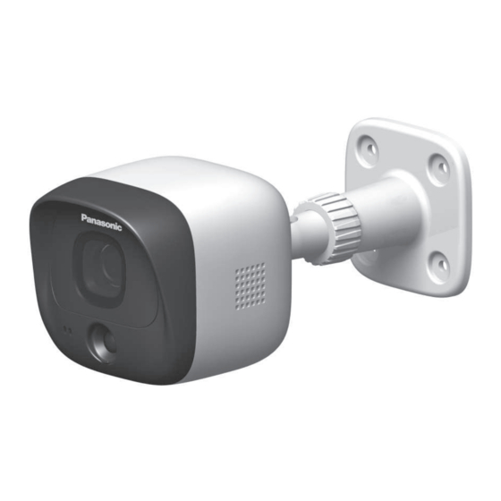
KX-HNC600FX
Model No.
Outdoor Camera
Advertisement
Table of Contents

Related Manuals for Panasonic KX-HNC600FX


Summary of Contents for Panasonic KX-HNC600FX
- Page 1 Outdoor Camera KX-HNC600FX Model No. Thank you for purchasing a Panasonic product. This document explains how to install the outdoor camera properly. For details about how to use the system, refer to the User’s Guide (page 27). Please read this document before using the unit and save it for future reference.
-
Page 2: Table Of Contents
Table of Contents Introduction Accessory information ........3 Important Information About this system .........5 For your safety ..........5 Important safety instructions ......6 For best performance ........6 Privacy and rights of portrait ......7 Other information .........7 Installation Location Wireless communication range ....9 Information about sensor features ....9 Information about night vision mode ..11 Installation location examples ....12... -
Page 3: Accessory Information
10 mm Large screw for attaching safety wire to wall 25 mm Sensor range cap Additional accessories Please contact your nearest Panasonic dealer for sales information. Accessory item Order number PNJA1159Z DC extension cord Designed for indoor use only. Do not use outdoors. - Page 4 Introduction Trademarks R microSDHC is a trademark of SD-3C, LLC. R iPhone and iPad are trademarks of Apple Inc., registered in the U.S. and other countries. R Android is a trademark of Google Inc. R Microsoft, Windows, and Internet Explorer are either registered trademarks or trademarks of Microsoft Corporation in the United States and/or other countries.
-
Page 5: Important Information
R Do not connect non-specified devices. designed to provide complete protection R When opening holes in walls for installation from property loss. Panasonic will not be or wiring, or when securing the power cord, held responsible in the event that property make sure you do not damage existing loss occurs while this system is in operation. -
Page 6: Important Safety Instructions
For best performance equipment that could be sensitive to external RF energy. Hub location/avoiding noise The hub and other compatible Panasonic CAUTION devices use radio waves to communicate with each other. Installation and location... -
Page 7: Privacy And Rights Of Portrait
Important Information R Do not place heavy objects on top of the Camera image quality product. R Camera images may have the following R When you leave the product unused for a characteristics. long period of time, unplug the product from –... - Page 8 Important Information Penalties may be applicable for incorrect disposal of this waste, in accordance with national legislation. For business users in the European Union If you wish to discard electrical and electronic equipment, please contact your dealer or supplier for further information. Information on Disposal in other Countries outside the European Union This symbol is only valid in the European...
-
Page 9: Installation Location
R The camera’s sensor features are not designed to be used in situations that require high reliability. We do not recommend use of the sensor features in these situations. R Panasonic takes no responsibility for any injury or damage caused by the use of the camera’s sensor features. - Page 10 Installation Location Detection range Visual sensor Infrared sensor Can detect motion anywhere in the visible Can detect motion only in part of the visible image. image (shown here in grey) R You can adjust the area detectable by the R You can adjust the area detectable by the visual sensor.
-
Page 11: Information About Night Vision Mode
Installation Location Direction of motion It is easier to detect objects that move sideways in front of the camera, and more difficult to detect objects that move directly toward the front of the camera. A It is difficult to detect movement directly towards the front of the camera. B It is easy to detect movement sideways in front of the camera. -
Page 12: Installation Location Examples
Installation Location Installation location examples I want to detect visitors approaching the house Refer to the table below for detecting visitors at an entrance or gate without detecting cars in the street. Ideal example Poor example Cars in the street are more likely to cause Approx. - Page 13 Installation Location I want to detect people entering the garage Refer to the table below for detecting people entering a garage without detecting cars in the street. Ideal example Poor example Visitors pass in front of the camera from side Cars in the street are more likely to cause to side, cars in the street are less likely to false detections.
-
Page 14: Do Not Install In These Locations
Installation Location Installing in the following areas may Do not install in these cause false detections locations R Areas where people approach directly from the front of the camera, such as narrow Installing in the following areas may walkways cause deformation, discolouration, Camera Difficult to detect malfunction, or operational failure... - Page 15 Installation Location R Areas affected by breezes from fans, air conditioning unit compressors, water heaters, or car exhaust (severe temperature variations may cause false detections) R Areas subject to severe weather, such as strong wind (camera shake can cause false detections) or rain (strong rain may be detected as an object moving in front of the camera)
-
Page 16: Setup
Setup Indicator Status Part names and functions Red, blinking slowly Live images are being viewed or recorded Red, blinking Camera is out of range of the hub, or device malfunction Amber, blinking Camera is not slowly registered to a hub You can configure the camera so that its LED indicator does not light during normal operation. -
Page 17: Confirming The Installation Area
Setup Before you can use the camera, it must be registered to the hub. Confirming the installation If the camera is not registered to a hub, the area camera’s LED indicator blinks slowly in amber. You can register each device by using the Before deciding where to install the camera, registration buttons or the [Home Network] carefully read the chapter “Installation... -
Page 18: Installation
Installation precautions R Do not install the camera on a ceiling. R Holes must be made in the wall for cables and wires to pass through. Panasonic takes no responsibility for issues related to opening holes in walls. R Make sure to waterproof the holes you make in the wall. - Page 19 Setup Remove debris. Installing the camera Attach the safety wire to the camera. R Place the ring of the safety wire (A) over the screw hole. R Place a washer (B) on top of the ring of the safety wire. Insert an anchor, tighten the screw, then R Tighten the screw (C) for the safety remove the screw to secure the anchor.
- Page 20 Setup Note: Attach the camera to the stand using the R Use the following template below when stand attachment hole on the rear or determining the location of the screw bottom of the camera, depending on the holes. direction you want to aim the camera. R Loosen the screw ( R Insert the tip of the stand (A) into the 37 mm...
- Page 21 Setup Adjust the camera angle. Attach the safety wire to the wall. R Place the ring of the safety wire (A) R Loosen the screw ( ) and then adjust on the wall. the camera to the desired angle. R Place the washer (B) on top of the R Tighten the screw ( ) while holding ring of the safety wire.
- Page 22 R Connect the AC adaptor (C) to the power outlet. Outdoors Indoors Note: R Use only the supplied Panasonic AC adaptor PNLV236CE. R Be sure to connect the DC cable plug and AC adaptor plug indoors. Note about power connections...
-
Page 23: Appendix
Appendix Testing the motion Adjusting the infrared detection range sensor range After you have installed the [Home Network] If there are objects that you do not want the app on your mobile device, you can use your infrared sensor to detect, you can adjust the mobile device to test the performance of the detectable area by attaching sensor range camera’s motion detection features. - Page 24 Appendix Approximate detection range (view when looking from above) Situation and cap types 20 °C 0 °C 30 °C When you want both sides of the camera to be detectable Standard cap (attached to the camera) When you want one (Example) Cap 1 (Example) Cap 1 (Example) Cap 1...
- Page 25 Appendix About the attachment angle of the sensor range cap Example 1 When there is an object on the right side of the viewable area that you do not want to be detected (such as trees): Attach one of caps 1-3 as shown in the example ( ) according to the area you do not want to be detected.
- Page 26 Appendix Replacing sensor range caps Remove the attached standard cap. Remove the desired sensor range cap from one of the 4 types (A) and attach it to the sensor (B). R When attaching, rotate the tab ( ) on the cap toward the top or at a 45-degree angle according to the type of cap or direction, and attach the cap on the camera, shown in the following illustration.
-
Page 27: Features Available When Using The [Home Network] App
– Sensor adjustment You can adjust the camera’s motion detection features, such as detection sensitivity and detection area. – Sensor integration www.panasonic.net/pcc/support/tel/ You can configure the camera’s sensor homenetwork/manual/ features to trigger other system events, such as camera recording , turning on an electric device (such as a lamp), etc. -
Page 28: Specifications
Appendix Vertical: facing forward - facing down approx. 60° Specifications (adjustable when mounting) R Dimensions (height ´ width ´ depth) R Standards Approx. 75 mm ´ 75 mm ´ 173 mm DECT (Digital Enhanced Cordless R Mass (weight) Telecommunications) Approx. 305 g R Frequency range 1.88 GHz –... - Page 29 Notes...
- Page 30 Notes...
- Page 31 Notes...
- Page 32 We recommend keeping a record of the following information to assist with any repair under warranty. Serial No. Date of purchase (found on the rear of the unit) Name and address of dealer Attach your purchase receipt here. © Panasonic Corporation 2016 PNQP1177YA CC0216WK1126...
Need help?
Do you have a question about the KX-HNC600FX and is the answer not in the manual?
Questions and answers