Table of Contents
Advertisement
Available languages
Available languages
Quick Links
Please Do Not Return This
Product to the Store!
Contact Escalade® Sports customer service department at:
Phone: 1-888-872-4625 Toll-Free!
Fax: 1-866-873-3536 Toll-Free!
E-mail: customerservice@escaladesports.com
Escalade® Sports products may be manufactured and/or licensed under the following patents.
6120397, 5816957, 5769744, 5119741, 4911085, 4717157, D460140, D420563, 8414431
Additional patents may be pending. One or more of the listed patents and/or pending patents may cover specific product.
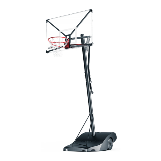
G - F O R C E 5 0 "
P O R T A B L E B A S K E T B A L L
MODEL NO.
B7007CF
2L-7641-00
2017 Escalade Sports
Advertisement
Table of Contents

Subscribe to Our Youtube Channel
Related Manuals for ESCALADE GOALIATH G-FORCE B7007CF


Summary of Contents for ESCALADE GOALIATH G-FORCE B7007CF
- Page 1 Fax: 1-866-873-3536 Toll-Free! E-mail: customerservice@escaladesports.com 2L-7641-00 Escalade® Sports products may be manufactured and/or licensed under the following patents. 6120397, 5816957, 5769744, 5119741, 4911085, 4717157, D460140, D420563, 8414431 2017 Escalade Sports Additional patents may be pending. One or more of the listed patents and/or pending patents may cover specific product.
-
Page 2: P R E - A S S E M B L Y T I P S
Please visit our Website at: E-mail: basketball@escaladesports.com www.escaladesports.com Mailing Address (correspondence only): Escalade Sports ON-LINE TROUBLE SHOOTING TECHNICAL ASSISTANCE PO Box 889 ON-LINE PARTS REQUESTS FREQUENTLY ASKED QUESTIONS ADDITIONAL ESCALADE ® SPORTS PRODUCT INFORMATION Evansville, IN 47706 2L-7641-00 2017 Escalade Sports... -
Page 3: Safety Instructions
SAFETY INSTRUCTIONS FAILURE TO FOLLOW THESE SAFETY INSTRUCTIONS MAY RESULT IN SERIOUS INJURY, PROPERTY DAMAGE AND WILL VOID WARRANTY. Owner must ensure that all players know and follow these rules for safe operation of the system. To ensure safety, do not attempt to assemble this system without following the instructions carefully. Check entire box and inside packing material for parts and/or additional instruction material. - Page 4 P A R T S L I S T ( N O T A C T U A L S I Z E ) BREAK AWAY RIM RIM NET BACKBOARD ASSEMBLY 50 X 33 BALLAST 4A-8059-30 4A-8069-00 3F-6070-00 3M-8991-00 (QTY. 1) (QTY.
- Page 5 P A R T S L I S T ( N O T A C T U A L S I Z E ) (Actuator Bar Cap Pre-installed) BOARD ARM CAP 3M-9017-00 (QTY. 6) (Pre-assembled to LOWER BOARD ARM Board Arms) UPPER BOARD ARM ACTUATOR BAR 8S-7713-20...
- Page 6 P A R T S L I S T ( N O T A C T U A L S I Z E ) POLE CAP 3M-8997-00 (QTY. 1) (Pre-assembled to ACTUATOR GRIP ACTUATOR LOCK ASSEMBLY SPRING Top Pole) 3M-9034-00 4A-8141-20 5V-6041-00 (QTY.
- Page 7 H A R D W A R E I D E N T I F I E R ( A C T U A L S I Z E ) (QTY. 3) HEX HEAD BOLT M10-1.5 X 220mm 1B-7085-00 (QTY. 1) HEX HEAD BOLT M10-1.5 X 210mm 1B-7080-00 (QTY.
- Page 8 H A R D W A R E I D E N T I F I E R ( A C T U A L S I Z E ) Philips Head Screw M6-1 X 60mm HEX LOCK NUT M6-1 1B-7123-00 2B-6803-00 (QTY.
- Page 9 HARDWARE NEEDED (ACTUAL SIZE) The following pages will have a picture of the Hardware Needed along with the Quantity, Part Number and Description. You can lay the hardware on the picture to identify the hardware. ASSEMBLY TIP HEX HEAD BOLT M10-1.5 X 65mm 1B-7081-00 (QTY.
- Page 10 HARDWARE NEEDED (ACTUAL SIZE) HEX HEAD BOLT M10-1.5 X 210mm 1B-7080-00 (QTY. 1) HEX LOCK NUT M10-1.5 WASHER M10 2B-6801-00 2B-6800-00 (QTY. 1) (QTY. 2) DETAIL A 2. Attach lower pole (12) to lower assembly. Line up the holes in the four tubes and lower pole and attach hardware as shown in Detail A.
-
Page 11: Tools Needed
HARDWARE NEEDED (ACTUAL SIZE) TOOLS NEEDED 16mm 16mm WASHER M10 HEX HEAD BOLT M10-1.5 X 25mm HEX LOCK NUT M10-1.5 2B-6800-00 2B-6801-00 1B-7082-00 (QTY. 2) (QTY. 4) (QTY. 2) 3. Finish securing lower pole (12) to lower assembly DETAIL A as shown. - Page 12 TOOLS NEEDED 4. Before Inserting Axle Bushings (5) into the lower assembly Steel Tube, align the bushings (5) so the groove goes over the tube weld seam without touching it. See Detail A & Detail B. Rubber 5. Use a wood block and Rubber Mallet to gently tap the Axle Wood Block Mallet Bushing into Steel Tube.
- Page 13 6. Insert Axle (4) into lower assembly Steel tube until both ends of the Axle stick out about the same distance on each side. Steel Tube...
- Page 14 NOTE: Inner Wheel Hub (6) and Outer wheel (8) are pre-assembled into Wheel (7) by the factory. If either of those parts have fallen out during shipping re-insert parts as shown in Detail A. 7. Slide Wheel (7) onto Axle (4). Repeat step to install the second wheel.
- Page 15 HARDWARE NEEDED (ACTUAL SIZE) 8. Insert Axle Rod (9), through Washer (10) and into Wheel assembly and axle until it reaches the other side of the Axle and wheel. Have a Second person hold second Wheel. WASHER M10 X 30mm 2B-6795-00 (QTY.
- Page 16 HARDWARE NEEDED (ACTUAL SIZE) TOOLS NEEDED 16mm 16mm HEX NUT M10-1.5 WASHER, LOCK INTERNAL-TOOTH WASHER M10 X 30mm 2B-6806-00 2B-6796-00 2B-6795-00 (QTY. 1) (QTY. 1) (QTY. 1) 9. Secure Axle Rod (9) with Washer (10), Lock Tooth Washer DETAIL A (43) and Hex Nut (11).
-
Page 17: Hardware Needed
HARDWARE NEEDED 10. Unscrew the Wheel cap (41) and remove, O-ring (42) is pre-attached to Wheel cap. Fill both wheels with water until 75% full (approx. 4 liters / 1 gal.) and screw Wheel cap back into the wheel with Wheel Plug key (57). Make sure that O-ring is attached to Wheel Cap. - Page 18 HARDWARE NEEDED (ACTUAL SIZE) 12. Attach Left Brace tube (19) and Right brace Tube (18). Match up the green color coded stickers on the Right Brace tube and the lower pole and match the color stickers on the Left Brace tube HEX HEAD BOLT M8-1.25 X 65mm 1B-7077-00 and Lower Pole as shown in Detail A.
-
Page 19: Side View
HARDWARE NEEDED (ACTUAL SIZE) 13. Secure ballast to lower assembly as shown in Detail A. Finger Tighten hardware. HEX HEAD BOLT M8-1.25 X 65mm NOTE: If needed use your thumb to push bolt 1B-7077-00 Hex Lock Nut M8-1.25 forward (see Detail B) and then down (QTY. - Page 20 HARDWARE NEEDED (ACTUAL SIZE) 14. Position Middle pole (50) with the Warning label facing forward, then slide Middle pole into Lower pole (12). Make sure that all (QTY. 1) holes are aligned in both poles. HEX HEAD BOLT M10-1.5 X 110mm 1B-7079-00 15.
- Page 21 HARDWARE NEEDED (ACTUAL SIZE) 16. Secure pole with hardware shown. Finger Tighten only. HEX HEAD BOLT M10-1.5 X 100mm 1B-7078-00 (QTY. 2) HEX NUT M10-1.5, WITH CAP WASHER _ CURVED M10 2B-6799-00 2B-6802-00 (QTY. 2) (QTY. 2) NOTE FINGER TIGHTEN ONLY! NOTE MAKE SURE HEADS OF THE BOLTS ARE INSERTED INTO...
- Page 22 TOOLS NEEDED TIGHTEN THIS HARDWARE SECOND. 13mm 13mm 17. In this Step you will begin to tighten the hardware from previous steps in the following sequence: First tighten hardware shown in Detail A. Second, tighten hardware shown in Detail B. TIGHTEN HARDWARE UNTIL SNUG.
- Page 23 TOOLS NEEDED 18. In this Step you will continue to tighten the hardware from previous steps: First tighten hardware shown in Detail A. Second, tighten hardware shown in Detail B. TIGHTEN HARDWARE TIGHT BUT DO NOT CRUSH TUBE. 16mm 17mm TIGHTEN THIS HARDWARE SECOND.
- Page 24 HARDWARE NEEDED (ACTUAL SIZE) TOOLS NEEDED HEX HEAD BOLT M10-1.5 X 110mm 1B-7079-00 16mm 16mm (QTY. 2) 19. Attach the reinforcement plate (37) to the front of the pole (on the side that has the Warning label) with 2 bolts (22). HEX LOCK NUT M10-1.5 2B-6801-00 Hex heads should be facing front of the unit.
- Page 25 HARDWARE NEEDED (ACTUAL SIZE) ACTUATOR ROLLER 3M-9035-00 (QTY. 1) HEX LOCK NUT M6-1 PHILIPS HEAD SCREW M6-1 X 60mm 2B-6803-00 1B-7123-00 (QTY. 1) (QTY. 1) TOOLS NEEDED 20. Insert Screw (46) through Actuator bracket, Actuator Roller (48) and through other side of Actuator bracket.
- Page 26 TOOLS NEEDED NOTE: If your Top Pole (51) has the Pole Cap (38) pre-installed skip step 21. 21. Set the top pole (51) on a piece of cardboard to protect the bottom of the pole. Insert the Pole Cap (38) at the top of the pole as shown in Detail A. Rubber 22.
- Page 27 HARDWARE NEEDED (ACTUAL SIZE) 23. Insert hardware as shown in Detail A & Detail B. FINGER TIGHTEN ONLY. NOTE: MAKE SURE HEADS OF THE BOLTS ARE INSERTED INTO THE CUT OUT OF THE POLE. WASHER _ CURVED M10 HEX NUT M10-1.5, WITH CAP 2B-6802-00 2B-6799-00 (QTY.
- Page 28 TOOLS NEEDED 24. In this Step you will begin to tighten the hardware from previous steps in the following sequence: First tighten hardware shown in Detail A. Second, tighten hardware shown in Detail B. 17mm TIGHTEN THIS HARDWARE SECOND. TIGHTEN THIS HARDWARE FIRST. NOTE MAKE SURE HEADS OF THE BOLTS ARE INSERTED INTO THE CUT OUT OF THE POLE, IF...
- Page 29 NOTE: NOTE: Rest the system above the bolts of the actuator bracket so the ladder does not Prepare a flat area that is clear of debris. Keep children away from the damage the warning label. assembly area. Two capable adults are needed for the following steps. 25.
- Page 30 HARDWARE NEEDED (ACTUAL SIZE) 28. With a helper still holding the pole, attach the arms to upper pole as shown in Detail A-C. Finger Tighten Nuts (29) only, you will tighten this hardware in the next page. WASHER M12 X 24mm OD HEX LOCK NUT M12-1.75 2B-6804-00 2B-6805-00...
-
Page 31: Important Note
HARDWARE NEEDED (ACTUAL SIZE) TOOLS NEEDED HEX HEAD BOLT M10-1.5 X 220mm 1B-7085-00 (QTY. 2) 16mm WASHER M10 HEX LOCK NUT M10-1.5 2B-6800-00 2B-6801-00 WASHER, NYLON (QTY. 4) 3M-9000-00 (QTY. 2) 16mm 19mm (QTY. 4) 29. Attach Backboard Box (26) to lower and upper arms as shown in Detail A & B. Make sure to put a (27) Nylon Washer in between the Arms and the Backboard Box. - Page 32 HARDWARE NEEDED (ACTUAL SIZE) 30. Insert bolt (20) through Washer (23), first upper arm, second upper arm, second Washer (23) and Nut (24) as shown. Tighten hardware on the upper arms until the nut makes contact with the ears but do not overtighten the nut.
- Page 33 31. Insert one end of the spring (55) into Spring bracket on the upper pole as shown in Detail A. 32. With the help of another person attach Spring (55) to upper board arms. With one hand tilt the upper arms towards the spring and hold arms in position, then with the other hand pull the spring toward the arms and hook it onto the Bolt as shown in Detail A &...
-
Page 34: Hardware Needed
HARDWARE NEEDED 33. With the assembly still facing down, attach the backboard as shown. Have a person hold the backboard while you insert the Hitch pins (33) into the backboard supports. See Details A & B. The hitch pins will keep the backboard in place and will be HITCH PIN completely secure once the Rim is attached. -
Page 35: Bottom View
HARDWARE NEEDED (ACTUAL SIZE) TOOLS NEEDED NOTE: Take protective coating off the backboard before attaching the Rim. 34. With the assembly still facing down, attach the Rim to the Backboard. Have a person hold the Rim in 16mm socket place while you place Washers (23) and Nuts (24) with 3”... - Page 36 36. Slide the Actuator Bar (53) through the Actuator Bracket, release the lever by pressing down and holding while inserting the Actuator Bar. See Detail A & B. 37. Engage the lock by letting go of the lever and allow actuator to lock into the bracket.
- Page 37 HARDWARE NEEDED (ACTUAL SIZE) TOOLS NEEDED HEX HEAD BOLT M10-1.5 X 220mm 1B-7085-00 (QTY. 1) 16mm WASHER M10 HEX LOCK NUT M10-1.5 2B-6800-00 2B-6801-00 (QTY. 2) (QTY. 1) 16mm DETAIL A SPRING NOT SHOWN FOR CLARITY. 38. Attach other end of the Actuator Bar (53) to the lower arms, as shown.
- Page 38 HARDWARE NEEDED TOOLS NEEDED 39. Insert Actuator Grip (31) into actuator bar until the handle is flush with the actuator bar, then line up the holes in the grip with the holes in the actuator bar and secure with two Screws (32) as Rubber shown in Detail A.
- Page 39 NOTE: This is a good time to clean the backboard (if needed). Use a damp microfiber towel or soft cotton cloth to clean the backboard. Do not use paper towels, harsh chemicals or anything that could potentially damage your backboard. 40.
- Page 40 42. Carefully move the system where you would like to place it and then Fill the Ballast about 75% full (approx. 95 liters / 25 gal.) with water. Make sure that the Ballast Cap washer (14) is in place before Screwing cap (13) in place. NOTE: Do not overfill the ballast.
- Page 41 System will be the purchaser’s responsibility. Shipping charges for replaced or warranted merchandise sent back to the customer from Escalade Sports factory must be prepaid by the customer in advance. If not, the replacement shipment will be sent out collect.
- Page 42 Téléphone: 1-888-872-4625 Appel gratuit! Télécopie: 1-866-873-3536 Appel gratuit! Courriel: customerservice@escaladesports.com Les produits Escalade® Sports peuvent être fabriqués et/ou licenciés sous les brevets suivants 2L-7641-00 6120397, 5816957, 5769744, 5119741, 4911085, 4717157, D460140, D420563, 8414431 D'autres brevets peuvent être en attente. Un ou plusieurs des brevets indiqués et/ou des brevets en 2017 Escalade Sports attente peuvent couvrir un produit spécifique.
- Page 43 Pour visionner une vidéo montrant comment assembler ce système de Veuillez ne pas retourner ce produit au magasin! basket-ball, veuillez visiter notre page YouTube à: Communiquez avec le service à la clientèle Escalade Sports à: https://www.youtube.com/watch?v=jw 1-888-872-4625 Téléphone : Appel gratuit! uQQaHTw6Q Télécopie:...
-
Page 44: Instructions De Sécurité
INSTRUCTIONS DE SÉCURITÉ LE NON-RESPECT DE CES INSTRUCTIONS DE SÉCURITÉ PEUT ENTRAÎNER DES BLESSURES GRAVES ET DES DOMMAGES MATÉRIELS, ET ANNULERA LA GARANTIE. Le propriétaire doit s'assurer que tous les joueurs connaissent et suivent ces règles pour garantir un fonctionnement sécurisé du système. Pour garantir la sécurité, n'essayez pas d'assembler ce système sans suivre attentivement les instructions. - Page 45 L I S T E D E S P I È C E S (P A S E N T A I L L E R É E L L E) MONTURE DÉTACHABLE FILET ASSEMBLAGE DE PANNEAU 50 X 33 BALLAST 4A-8059-30 4A-8069-00...
- Page 46 L I S T E D E S P I È C E S (P A S E N T A I L L E R É E L L E) (Capuchon de la barre de l'actionneur préinstallé) CAPUCHON DE BRAS DE PANNEAU 3M-9017-00 (QTÉ.
- Page 47 L I S T E D E S P I È C E S (P A S E N T A I L L E R É E L L E) CAPUCHON DU POTEAU 3M-8997-00 (QTÉ. 1) ENSEMBLE DE (Préassemblé au POIGNÉE DE L'ACTIONNEUR RESSORT poteau supérieur)
- Page 48 I D E N T I F I A N T D E Q U I N C A I L L E R I E (T A I L L E R É E L L E) (QTÉ. 3) BOULON À...
- Page 49 I D E N T I F I A N T D E Q U I N C A I L L E R I E (T A I L L E R É E L L E) CONTRE-ÉCROU VIS À TÊTE PHILLIPS M6-1 X 60mm HEXAGONAL M6-1 1B-7123-00 2B-6803-00...
- Page 50 QUINCAILLERIE NÉCESSAIRE (TAILLE RÉELLE) Les pages suivantes auront une illustration de la quincaillerie nécessaire ainsi que la quantité, le numéro de pièce et la description. Vous pouvez étaler CONSEIL la quincaillerie sur l'illustration pour identifier la D'ASSEMBLAGE quincaillerie. BOULON À TÊTE HEXAGONALE M10-1.5 X 65mm 1B-7081-00 (QTÉ.
- Page 51 QUINCAILLERIE NÉCESSAIRE (TAILLE RÉELLE) BOULON À TÊTE HEXAGONALE M10-1.5 X 210mm 1B-7080-00 (QTÉ. 1) Contre-écrou hexagonal RONDELLE M10 M10-1.5 2B-6800-00 2B-6801-00 (QTÉ. 2) (QTÉ. 1) DÉTAIL A 2. Fixez le poteau inférieur (12) à l'assemblage inférieur. Alignez les trous dans les quatre tubes et le poteau inférieur, et fixez la quincaillerie comme illustré...
-
Page 52: Outils Nécessaires
QUINCAILLERIE NÉCESSAIRE (TAILLE RÉELLE) OUTILS NÉCESSAIRES CONTRE-ÉCROU 16mm 16mm RONDELLE M10 BOULON À TÊTE HEXAGONALE HEXAGONAL 2B-6800-00 M10-1.5 X 25mm M10-1.5 (QTÉ. 4) 1B-7082-00 2B-6801-00 (QTÉ. 2) (QTÉ. 2) 3. Finissez de fixer le poteau inférieur (12) à l'assemblage inférieur comme illustré. Serrez DÉTAIL A toute la quincaillerie à... - Page 53 OUTILS NÉCESSAIRES Avant d'insérer les bagues d'essieu (5) dans le tube en acier de l'assemblage inférieur, alignez les bagues (5) de manière à ce que la rainure dépasse le joint de soudure du tube sans le toucher. Voir Détail A et Détail B Utilisez un bloc de bois et un maillet en caoutchouc pour taper Maillet en Bloc de bois...
- Page 54 6. Insérez l'essieu (4) dans le tube en acier de l'ensemble inférieur jusqu'à ce que les deux extrémités de l'essieu ressortent à environ la même distance de chaque côté. Tube en acier...
- Page 55 REMARQUE: Le moyen de roue intérieur (6) et la roue extérieure (8) sont préassemblés dans la roue (7) par l'usine. Si l'une de ces pièces est tombée pendant l'expédition, réinsérez les pièces comme illustré au Détail 7. Glissez la roue (7) sur l'essieu (4). Répétez l'étape pour installer la seconde roue.
- Page 56 QUINCAILLERIE NÉCESSAIRE (TAILLE RÉELLE) 8. Insérez la tige de l'essieu (9) dans la rondelle (10) et dans l'ensemble de roues et l'essieu jusqu'à ce qu'elle atteigne l'autre côté de l'essieu et de la roue. Faites en sorte qu'une seconde personne tienne la seconde roue RONDELLE M10 X 30mm 2B-6795-00...
- Page 57 QUINCAILLERIE NÉCESSAIRE (TAILLE RÉELLE) OUTILS NÉCESSAIRES 16mm 16mm RONDELLE, DE BLOCAGE INTERNE-DENTÉE ÉCROU HEXAGONAL M10-1.5 RONDELLE M10 X 30mm 2B-6806-00 2B-6796-00 2B-6795-00 (QTÉ. 1) (QTÉ. 1) (QTÉ. 1) Fixez la tige de l'essieu (9) avec la rondelle (10), la DÉTAIL A rondelle de blocage dentée (43) et l'écrou hexagonal (11).
- Page 58 QUINCAILLERIE NÉCESSAIRE 10. Dévissez l'enjoliveur de roue (41) et retirez-le, le joint torique (42) est déjà fixé à l'enjoliveur de roue. Remplissez les deux roues d'eau jusqu'à 75 % (environ 4 litres /1 gallon) et revissez le capuchon de roue dans la roue avec la clé...
- Page 59 QUINCAILLERIE NÉCESSAIRE (TAILLE RÉELLE) 12. Fixez le tube de support gauche (19) et le tube de support droit (18). Faites correspondre les autocollants à code couleur verts sur le tube de support droit et le poteau inférieur, et faites correspondre les autocollants BOULON À...
- Page 60 QUINCAILLERIE NÉCESSAIRE (TAILLE RÉELLE) 13. Fixez le ballast à l'assemblage inférieur comme illustré au Détail A. Serrez la quincaillerie à la main. BOULON À TÊTE HEXAGONALE M8-1.25 X 65mm 1B-7077-00 REMARQUE: Si nécessaire, utilisez votre pouce CONTRE-ÉCROU HEXAGONAL RONDELLE M8 (QTÉ.
- Page 61 QUINCAILLERIE NÉCESSAIRE (TAILLE RÉELLE) 14. Positionnez le poteau central (50) avec l'étiquette d'avertissement face vers l'avant, puis faites coulisser le poteau central dans le (QTÉ. 1) poteau inférieur (12). Assurez-vous que tous les trous sont BOULON À TÊTE HEXAGONALE M10-1.5 X 110mm alignés dans les deux poteaux.
- Page 62 QUINCAILLERIE NÉCESSAIRE (TAILLE RÉELLE) 16. Fixez le poteau avec la quincaillerie indiquée. Serrez uniquement à la main. BOULON À TÊTE HEXAGONALE M10-1.5 X 100mm 1B-7078-00 (QTÉ. 2) ÉCROU HEXAGONAL M10-1,5, RONDELLE _ COURBÉE M10 AVEC BOUCHON 2B-6802-00 2B-6799-00 (QTÉ. 2) SERREZ UNIQUEMENT À...
- Page 63 OUTILS NÉCESSAIRES SERREZ CETTE QUINCAILLERIE EN DEUXIEME 13mm 13mm 17. Dans cette étape, vous commencerez à serrer la quincaillerie des étapes précédentes dans la séquence suivante: Serrez d'abord la quincaillerie illustrée au Détail A. Puis, serrez la quincaillerie illustrée au Détail B. SERREZ LA QUINCAILLERIE JUSQU'À...
- Page 64 OUTILS NÉCESSAIRES 18. Dans cette étape, vous commencerez à serrer la quincaillerie des étapes précédentes : Serrez d'abord la quincaillerie illustrée au Détail A. Puis, serrez la quincaillerie illustrée au Détail B. SERREZ LA QUINCAILLERIE MAIS N'ÉCRASEZ PAS LE TUBE. 16mm 17mm SERREZ CETTE QUINCAILLERIE EN DEUXIÈME.
- Page 65 QUINCAILLERIE NÉCESSAIRE (TAILLE RÉELLE) OUTILS NÉCESSAIRES BOULON À TÊTE HEXAGONALE M10-1.5 X 110mm 1B-7079-00 16mm 16mm (QTÉ. 2) 19. Fixez la plaque de renfort (37) à l'avant du poteau (sur le côté qui présente l'étiquette d'avertissement) avec 2 boulons (22). Les têtes CONTRE-ÉCROU HEXAGONAL hexagonales doivent être placées à...
- Page 66 QUINCAILLERIE NÉCESSAIRE (TAILLE RÉELLE) ROULEAU DE L'ACTIONNEUR 3M-9035-00 (QTÉ. 1) VIS À TÊTE PHILLIPS CONTRE-ÉCROU HEXAGONAL M6-1 X 60mm M6-1 1B-7123-00 2B-6803-00 (QTÉ. 1) (QTÉ. 1) OUTILS NÉCESSAIRES 20. Insérez la vis (46) dans le support de l'actionneur, le rouleau de l'actionneur (48) et l'autre côté...
- Page 67 REMARQUE: : Si votre poteau supérieur (51) a le capuchon de poteau (38) préinstallé, sautez l'étape 21. OUTILS NÉCESSAIRES 21. Mettez le poteau supérieur (51) sur un morceau de carton pour protéger le bas du poteau. Insérez le capuchon du poteau (38) en haut du poteau comme illustré...
- Page 68 QUINCAILLERIE NÉCESSAIRE (TAILLE RÉELLE) 23. Insérez la quincaillerie comme illustré au Détail & Détail B. SERREZ UNIQUEMENT À LA MAIN. REMARQUE: ASSUREZ-VOUS QUE LES TÊTES DES BOULONS SONT INSÉRÉES DANS LA DÉCOUPE DU POTEAU. RONDELLE _ COURBÉE M10 ÉCROU HEXAGONAL M10-1,5, AVEC BOUCHON 2B-6802-00 (QTÉ.
- Page 69 OUTILS NÉCESSAIRES 24. Dans cette étape, vous commencerez à serrer la quincaillerie des étapes précédentes dans la séquence suivante : Serrez d'abord la quincaillerie illustrée au Détail A. Puis, serrez la quincaillerie illustrée au Détail 17mm SERREZ CETTE QUINCAILLERIE EN DEUXIÈME. SERREZ CETTE QUINCAILLERIE EN PREMIER.
-
Page 70: Vue Latérale
REMARQUE: REMARQUE: Laissez le système reposer sur les boulons du support de l'actionneur afin que l'échelle Préparez une surface plane exempte de débris. Tenez les enfants éloignés de la zone n'endommage pas l'étiquette d'avertissement. d'assemblage. Deux adultes compétents sont nécessaires pour les étapes suivantes. 25. - Page 71 QUINCAILLERIE NÉCESSAIRE (TAILLE RÉELLE) 28. Toujours avec l'aide d'un assistant pour tenir le poteau, fixez les bras au poteau supérieur comme illustré aux Détails A et C. Serrez les écrous (29) à la main seulement, vous CONTRE-ÉCROU HEXAGONAL RONDELLE M12 X 24mm OD serrerez cette quincaillerie à...
-
Page 72: Remarque Importante
QUINCAILLERIE NÉCESSAIRE (TAILLE RÉELLE) OUTILS NÉCESSAIRES BOULON À TÊTE HEXAGONALE M10-1.5 X 220mm 1B-7085-00 (QTÉ. 2) 16mm RONDELLE M10 CONTRE-ÉCROU HEXAGONAL 2B-6800-00 M10-1.5 RONDELLE, NYLON (QTÉ. 4) 2B-6801-00 3M-9000-00 16mm 19mm (QTÉ. 2) (QTÉ. 4) 29. Fixez le boîtier du panneau (26) aux bras inférieurs et supérieurs comme illustré aux Détails A et B. Assurez-vous de mettre une rondelle en nylon (27) entre les bras et le boîtier du panneau. - Page 73 QUINCAILLERIE NÉCESSAIRE (TAILLE RÉELLE) 30. Insérez le boulon (20) dans la rondelle (23), le premier bras supérieur, le second bras supérieur, la seconde rondelle (23) et l'écrou (24) comme illustré. Serrez la quincaillerie sur les bras supérieurs jusqu'à ce que l'écrou entre en contact avec les pattes, mais ne serrez pas trop l'écrou.
- Page 74 31. Insérez une extrémité du ressort (55) dans le support de ressort sur le poteau supérieur comme illustré au Détail 32. Avec l'aide d'une autre personne, fixez le ressort (55) à bras de panneau supérieurs. Avec une main, inclinez les bras supérieurs vers le ressort et tenez les bras en position, puis avec l'autre main, tirez le ressort vers les bras et accrochez-le sur le boulon comme illustré...
- Page 75 QUINCAILLERIE NÉCESSAIRE 33. Avec l'assemblage toujours face vers le bas, fixez le panneau comme illustré. Faites-vous aider par une personne pour tenir le panneau tandis que vous insérez les goupilles d'attelage (33) dans les supports du panneau. Voir Détails A et B. Les GOUPILLE D'ATTELAGE goupilles d'attelage garderont le panneau 7B-6577-00...
- Page 76 QUINCAILLERIE NÉCESSAIRE (TAILLE RÉELLE) REMARQUE: Retirez le revêtement de protection du OUTILS NÉCESSAIRES panneau avant de fixer la monture 34. Avec l'assemblage toujours face vers le bas, fixez la monture au panneau. Faites-vous aider par une personne pour tenir la Douille de 16mm monture en place tandis que vous posez les rondelles (23) et les avec extension...
- Page 77 36. Faites coulisser la barre de l'actionneur (53) dans le support de l'actionneur, relâchez le levier en appuyant et en maintenant appuyé tout en insérant la barre de l'actionneur. Voir Détails A et B. 37. Verrouillez la gâchette en lâchant le levier et laissez l'actionneur se verrouiller dans le support.
- Page 78 QUINCAILLERIE NÉCESSAIRE (TAILLE RÉELLE) OUTILS NÉCESSAIRES BOULON À TÊTE HEXAGONALE M10-1.5 X 220mm 1B-7085-00 (QTÉ. 1) 16mm CONTRE-ÉCROU HEXAGONAL RONDELLE M10 M10-1.5 2B-6800-00 2B-6801-00 (QTÉ. 2) 16mm (QTÉ. 1) DÉTAIL A LE RESSORT N'EST PAS ILLUSTRÉ À DES 38. Fixez l'autre extrémité à la barre de FINS DE CLARTÉ.
- Page 79 OUTILS NÉCESSAIRES QUINCAILLERIE NÉCESSAIRE 39. Insérez la poignée de l'actionneur (31) dans la barre de l'actionneur jusqu'à ce que la poignée affleure la barre de l'actionneur, puis alignez les trous dans la poignée avec les trous dans la barre Maillet en de l'actionneur et fixez avec deux vis (32) comme Phillips caoutchouc...
- Page 80 REMARQUE: C'est le bon moment pour nettoyer le panneau (si nécessaire). Utilisez une serviette en microfibres humide ou un chiffon en coton doux pour nettoyer le panneau. N'utilisez pas d'essuie- tout, des produits chimiques agressifs ou quoi que ce soit qui pourrait éventuellement endommager votre panneau.
- Page 81 42. Déplacez soigneusement le système où vous souhaiteriez le placer, puis remplissez le ballast d'environ 75 % (environ 95 litres / 25 gal) avec de l'eau. Assurez-vous que la rondelle du capuchon du ballast (14) est en place avant de visser le capuchon (13) en place. REMARQUE:Ne remplissez pas trop le ballast.
- Page 82 Escalade Sports n'assume aucune autre obligation ou responsabilité de la part de l'acheteur, tout comme Escalade Sports n'assume et n'autorise pas non plus une autre personne à assumer en son nom toute autre responsabilité en lien avec les marchandises vendues.
Need help?
Do you have a question about the GOALIATH G-FORCE B7007CF and is the answer not in the manual?
Questions and answers
Locking mechanism replacement