Advertisement
Table of Contents
- 1 Table of Contents
- 2 Important Safety Instructions
- 3 System Parts
- 4 Installation Mounting Bracket
- 5 Installation Camera Wiring
- 6 Installation Mounting Bracket Cont
- 7 Camera Installation
- 8 Camera Positioning
- 9 Monitor Installation
- 10 Pairing
- 11 Picture Control
- 12 Troubleshooting
- 13 Specifications
- Download this manual
Advertisement
Table of Contents

Subscribe to Our Youtube Channel
Related Manuals for Furrion FOS48TA-BL


Summary of Contents for Furrion FOS48TA-BL
- Page 1 Digital Wireless Observation System Operating and Installation Instructions This manual is for use with Furrion FOS48TA-BL Digital Wireless Observation System Furrion FOS48TAPK-BL Digital Wireless Observation System With FRCBRKT-BL Mounting Bracket pre-installed.
- Page 2 This means the Furrion camera unit eliminates the interferences which other analogue signal systems are subject to, meaning the Furrion digital system gives you a clearer picture of what is behind you no matter where you are.
-
Page 3: Table Of Contents
Contents IMPORTANT SAFETY INSTRUCTIONS..............4 System Parts......................5 Installation ...................6-7 Mounting Bracket Installation ..................7 Camera Wiring Installation ................8 Mounting Bracket cont Camera Installation....................9 Camera Positioning....................10 Monitor Installation....................11 Pairing......................12 Picture Control.......................13 Trouble Shooting....................14 Specifications....................15... -
Page 4: Important Safety Instructions
There are no user serviceable parts Connect rear the camera to a 8- in the Furrion Digital Wireless Obser- 30V DC circuit only. vation System. Do not disassemble or Ensure correct polarity of DC power attempt any repairs. -
Page 5: System Parts
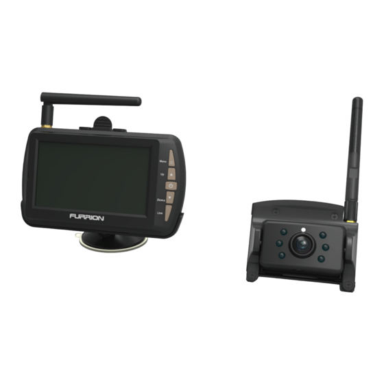
System Parts FOS48TAPK-BL Digital Wireless Observation System LCD Monitor Monitor Stand Monitor Power Cable Camera FRCBRKT-BL Digital Wireless Observation System Camera Bracket Camera Power Camera Bracket Gasket Cable... -
Page 6: Installation Mounting Bracket
Installation Mounting Bracket (If the FRCBRKT-BL Mounting is pre-installed please go to page 9) Suitable installation position.. Caution • Mount the camera directly above • Ensure there are no electrical the red running lights. cables, gas lines, pipes or other im- •... -
Page 7: Installation Camera Wiring
Installation Mounting Bracket Use the Bracket Gasket to Feed the supplied 6 Camera mark and outline where the centre Power Cable through the gasket. hole will be drilled then drill a 5/8 Ensure the bare wire end of the cable th”... -
Page 8: Installation Mounting Bracket Cont
Installation Mounting Bracket Mount the gasket & bracket to the Fix the Gasket & Bracket to the rear of the vehicle. Ensure that the rear of the vehicle using 4 x #2 head Camera Power Cable does not get 3/4” self tapping screws. (other screws caught between the vehicle wall &... -
Page 9: Camera Installation
Installation Camera Installation FRCBRKT-BL Pre-install only If installing to a pre-installed FRCBRKT-BL Mounting Bracket, remove the cover by unscrewing the 2 screws. Locate the Camera Power Con- Ensure the camera antenna is nector from within the Bracket and secured tight. connect it to the Camera Plug. -
Page 10: Camera Positioning
Installation Camera Positioning The camera can be tilted up & down to obtain the best viewing angle. Positioning the Camera • Adjust the camera up or down then check the view via the monitor. • If the camera is to be used as park- ing camera, part of the vehicle, such as the bumper, should be visible on the monitor. -
Page 11: Monitor Installation
Installation Monitor Installation Positioning the Monitor • Ensure the the is placed so that it does not obstruct vision when driving. • Do not place in an area where it might interfere with driving. • The surface area should be clean, smooth & flat. With the lock open, Press mount down Push the mount lock... -
Page 12: Pairing
Operation Pairing After installation, the camera & monitor need to be paired. This only needs to be done once. Menu/ Return Menu Power/ Confirm Down Down Line Line Pairing procedure Ensure both the camera and monitor have power supplied. The vehicle may need to be running 1. -
Page 13: Picture Control
Operation Pairing PAIRING FAILED will appear on the monitor after 13 seconds if the pairing proce- dure has been unsuccessful. *For better pairing results, bring the monitor closer to the camera. Unpairing To unpair the camera from the monitor, exit the menu, press & hold Down for 5 seconds. -
Page 14: Troubleshooting
Troubleshooting Problem Solution / Issue Monitor won’t turn on -Check that power cable is connected -Check the cigarette lighter has 12-14V DC Output -Check the fuse in the cigarette socket adaptor Camera & Monitor won’t -Check if the camera is receiving power pair -Reduce the distance between the camera &... -
Page 15: Specifications
Camera Monitor Voltage DC8-30V DC8-30V Current ≤300mA ≤200mA Standby Current ≤1mA Wireless Range ≤300M (outdoors) ≤300M (outdoors) Wireless Frequency 2.4Ghz Image Sensor 1/4” Color CMOS VGA LCD Display 4.3” 480*272 Camera Max 25frames/sec VGA f1.7mm, F2.0 View Distance ≥1.5m Brightness ≥ 2Lux Receiver Sensitivity -78±3dBm Working Temperature... - Page 16 This product is backed by Furrions 12 month product warranty See warranty card for terms & conditions. Furrion reserve the right to alter the information in this document without prior notice. Furrion shall not be liable for technical or editorial errors or omissions contained herein.
Need help?
Do you have a question about the FOS48TA-BL and is the answer not in the manual?
Questions and answers