Table of Contents

Subscribe to Our Youtube Channel
Related Manuals for Moxa Technologies IEX-402-SHDSL-T

Summary of Contents for Moxa Technologies IEX-402-SHDSL-T
- Page 1 IEX-402-SHDSL Series Quick Installation Guide Moxa Managed SHDSL Ethernet Extender Version 2.2, January 2021 Technical Support Contact Information www.moxa.com/support 2021 Moxa Inc. All rights reserved. P/N: 1802004020013 *1802004020013*...
-
Page 2: Package Checklist
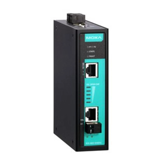
Overview The Moxa IEX-402-SHDSL series Ethernet Extender consists of one 10/100BaseT(x) port and a DSL interface that provides an economical solution for your Ethernet connections. Utilizing SHDSL technology over copper wires, the IEX-402-SHDSL series supports data rates of up to 15.3 Mbps and long transmission distance of over 8 km. - Page 3 IEX-402-SHDSL Panel Layout Front Panel View 1. Terminal block for power input (PWR1, PWR2) 2. Power input PWR1/PWR2 LED 3. State LED 4. Fault LED 5. 10/100BaseT(X) Port 6. DSL speed/SNR LED 7. Detachable 2-contact DSL Port 8. Link/ACT LED 9.
- Page 4 Mounting Dimensions (unit = mm [inches]) - 4 -...
-
Page 5: Din-Rail Mounting
DIN-Rail Mounting The aluminum DIN-Rail attachment plate should already be fixed to the back panel of the IEX-402-SHDSL when you take it out of the box. If you need to reattach the DIN-Rail attachment plate, make sure the stiff metal spring is situated towards the top, as shown in the following figures. -
Page 6: Wiring Requirement
NOTE Before tightening the screws into the wall, make sure the screw head and shank size are suitable by inserting the screw into one of the keyhole-shaped apertures of the wall mounting plates. Do not screw the screws in completely—leave about 2 mm to allow room for sliding the wall mount panel between the wall and the screws. -
Page 7: Wiring The Redundant Power Inputs
Wiring the Redundant Power Inputs Both power inputs can be connected simultaneously to live DC power sources. If one power source fails, the other live source acts as a backup, and automatically supplies the IEX-402-SHDSL with power. The two 2-contact terminal block connectors on the IEX's top panel are used for IEX's two DC power inputs. - Page 8 RJ45 (8-pin) to RJ45 (8-pin) Straight-Through Cable Wiring RJ45 (8-pin) to RJ45 (8-pin) Cross-Over Cable Wiring DSL Port Connection The DSL port located on the IEX-402-SHDSL has two connection options. One is the RJ45 connector interface (2-wire on pin 4 and pin 5), the other is the screw detachable interface.
- Page 9 RS-232 Console Port Connection The IEX-402-SHDSL has one RS-232 (10-pin RJ45) console port, located on the top panel. Use either an RJ45-to-DB9 (see the cable following wiring diagrams) to connect the IEX-402-SHDSL‘s console port to your PC’s COM port. You may then use console terminal software, such as Moxa PComm Terminal Emulator, to access the IEX-402-SHDSL’S serial console.
-
Page 10: Restore Factory Defaults Button
Restore Factory Defaults Button Press and hold the Reset button for 5 seconds to load the factory default settings. Use a pointed object, such as a straightened paper clip or toothpick, to depress the Reset button. This will cause the STATE LED to blink once a second. -
Page 11: Led Indicators
LED Indicators Color State Description Power is being supplied to the power input PWR1 PWR1 AMBER Power is not being supplied to the power input PWR1 Power is being supplied to the power input PWR2 PWR2 AMBER Power is not being supplied to the power input PWR2 System has passed self-diagnosis test on boot-up and is ready to run... -
Page 12: Specifications
DSL Speed/SNR LED Indicator Five Levels of SNR/SPEED Setting Turbo Speed STD Speed (K bits) (K bits) 10297 – 15304 4609 – 5760 5697 – 10296 3073 – 4608 3457 – 5696 2049 – 3072 1025 – 3456 769 – 2048 192 –... - Page 13 Environmental Limits Operating Temperature -10 to 60°C (32 to 140°F); -40 to 75°C (-40 to 167°F ) for -T models Storage Temperature -40 to 85°C (-40 to 185°F) Ambient Relative 5% to 95% (non-condensing) Humidity Altitude Up to 2000 m, contact Moxa for products guaranteed to function at higher altitudes Regulatory Approvals Safety...
Need help?
Do you have a question about the IEX-402-SHDSL-T and is the answer not in the manual?
Questions and answers