Table of Contents
Advertisement
Quick Links
We advise you to read this manual carefully, which contains all the instructions for
maintaining the appliance's aesthetic and functional qualities.
For further information on the product: www.smeg.com
Contents
ORIGINAL INSTRUCTIONS
4
4
8
8
8
8
8
9
10
10
11
11
12
12
13
13
15
17
17
18
19
21
22
26
27
28
30
30
32
34
34
37
42
47
48
3
Advertisement
Table of Contents

Related Manuals for Smeg SUK91MBL9


Summary of Contents for Smeg SUK91MBL9
-
Page 1: Table Of Contents
5.3 Positioning 5.4 Electrical connection 5.5 Instructions for the installer ORIGINAL INSTRUCTIONS We advise you to read this manual carefully, which contains all the instructions for maintaining the appliance’s aesthetic and functional qualities. For further information on the product: www.smeg.com... -
Page 2: Instructions
Instructions 1 Instructions not be carried out by unsupervised children. 1.1 General safety instructions • Be aware of how rapidly the cooking zones heat up. Do not Risk of personal injury place empty pans on the heat. • During use the appliance and its Danger of overheating. - Page 3 Instructions compartment (where present) of a qualified technician. when the oven is on and still hot. • If the power supply cable is • The items inside the storage damaged, contact technical compartment could be very hot support immediately and they will after using the oven.
- Page 4 Instructions • Never leave objects on the substances such as lemon juice or cooking surface. vinegar on the hob. • DO NOT USE THE APPLIANCE • Do not put empty pans or frying TO HEAT ROOMS FOR ANY pans on switched on cooking REASON.
- Page 5 Instructions detergents (e.g. scouring • Use cables withstanding a powders, stain removers and temperature of at least 90 °C. metallic sponges) on glass parts. • The tightening torque of the • Do not wash the removable screws of the terminal board components such as the hob leads must be 1.5 - 2 Nm.
-
Page 6: Manufacturer Liability
Instructions 1.2 Manufacturer liability 1.5 This user manual The manufacturer declines all liability This user manual is an integral part of for damage to persons or property the appliance and must therefore be caused by: kept in its entirety and within the user's reach for the whole working •... -
Page 7: How To Read The User Manual
Instructions • Deliver the appliance to the 1.7 How to read the user manual appropriate recycling centre for This user manual uses the following reading electrical and electronic conventions: equipment waste, or return it to Instructions the retailer when purchasing an General information on this user equivalent product, on a one for manual, on safety and final... -
Page 8: To Save Energy
Instructions 1.8 To save energy 1.9 Information for European Control Bodies • Only preheat the appliance if the recipe requires you to do so. Fan forced mode • Unless otherwise indicated on the the ECO function used to define the energy package, defrost frozen foods efficiency class complies with the specifications of European standard EN... -
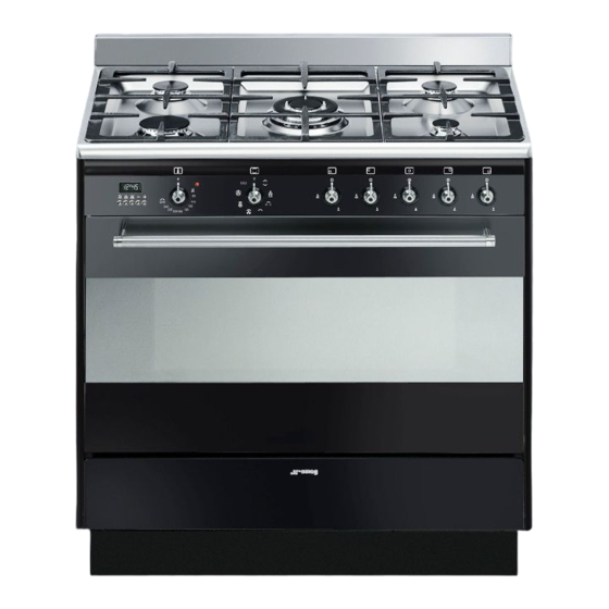
Page 9: Description
Description 2 Description 2.1 General Description 1 Upstand 6 Door 2 Cooking hob 7 Fan 3 Control panel 8 Storage compartment 4 Oven light Rack/tray support frame shelf 5 Seal... -
Page 10: Cooking Hob
Description 2.2 Cooking hob AUX = Auxiliary R = Rapid SR = Semi-rapid UR = Ultra rapid 2.3 Control panel 1 Programmer clock 3 Indicator light For displaying the current time, setting The indicator light comes on to indicate that programmed cooking operations and the the oven is heating up. -
Page 11: Other Parts
Description 5 Hob burner knobs The fan causes a steady outflow of air that exits from the rear of the appliance and Useful for lighting and adjusting the hob which may continue for a brief period of burners. time even after the appliance has been Press and turn the knobs anti-clockwise to turned off. - Page 12 Description Deep tray Rack Useful for collecting fat from foods placed Useful for supporting containers with food on the rack above. during cooking. Tray rack Some models are not provided with all accessories. The accessories intended to come into contact with food are made of materials that comply with the provisions of current legislation.
-
Page 13: Use
3 Use Improper use Risk of damage to surfaces Instructions • Do not cover the bottom of the oven High temperature inside the oven cavity with aluminium or tin foil sheets. during use Danger of burns • If you wish to use greaseproof paper, place it so that it will not interfere with the •... - Page 14 Malfunctions High temperature inside the oven during use Any of the following indicate a malfunction and you should contact a service centre: Danger of fire or explosion • Yellowing of the burner plate. • Do not spray any spray products near •...
-
Page 15: Using The Accessories
3.1 Using the accessories Racks and trays Racks and trays have to be inserted into the Ring reducers side guides until they come to a complete The ring reducers have to be placed on the stop. The mechanical safety locks that hob grids. -
Page 16: Using The Storage Compartment
The burner may go out when the knob is Practical tips for using the hob released: In this case, the thermocouple has For better burner efficiency and to minimise not heated up sufficiently. Wait a few gas consumption, use pans with lids and of moments and repeat the operation. -
Page 17: Using The Oven
3.4 Using the oven Fan + lower element The combination of the fan with just Switching on the oven the lower heating element allows To switch on the oven: cooking to be completed more 1. Select the cooking function using the rapidly. - Page 18 Fan with grill The air produced by the fan softens This function is particularly suitable the strong heatwave generated by for cooking on a single shelf with the grill, grilling perfectly even very low energy consumption. thick foods. Perfect for large cuts of It is recommended for all types of meat (e.g.
-
Page 19: Cooking Advice
3.5 Cooking advice Advice for cooking desserts/pastries and biscuits General advice • Use dark metal moulds: They help to • Use a fan assisted function to achieve absorb the heat better. consistent cooking at several levels. • The temperature and the cooking time •... -
Page 20: Digital Programmer
3.6 Digital programmer Setting the time If the time is not set, the oven will not switch on. On the first use, or after a power failure, the digits will be flashing on the appliance’s display. 1. Press the keys at the same time. - Page 21 Timed cooking 6. Press the keys at the same time to reset the programmer clock. Timed cooking is the function which allows a cooking operation to be started and then ended after It is not possible to set a cooking a specific length of time set by the time of more than 10 hours.
- Page 22 Minute minder timer 3. Use the key to set the required minutes. The minute minder timer does not stop the cooking operation but 4. Wait approx. 5 seconds without pressing rather informs the user when the set any key in order for the function to time has run out.
- Page 23 Cooking information table Runner Weight Temperature Food Function position from Time (minutes) (Kg) (°C) the bottom Lasagne 3 - 4 Static 220 - 230 45 - 50 Pasta bake 3 - 4 Static 220 - 230 45 - 50 Roast veal Turbo/Fan assisted 180 - 190 90 - 100...
-
Page 24: Cleaning And Maintenance
Cleaning and maintenance 4 Cleaning and maintenance Ordinary daily cleaning Always use specific products only that do Instructions not contain abrasives or chlorine-based acids. Pour the product onto a damp cloth Improper use and wipe the surface, rinse thoroughly and Risk of damage to surfaces dry with a soft cloth or a microfibre cloth. -
Page 25: Cleaning The Hob
Cleaning and maintenance 4.1 Cleaning the hob Igniters and thermocouples For correct operation the igniters and Cooking hob grids thermocouples must always be perfectly Remove the grids and clean them in clean. Check them frequently and clean lukewarm water and non-abrasive them with a damp cloth if necessary. -
Page 26: Cleaning The Door
Cleaning and maintenance 4.2 Cleaning the door 3. To reassemble the door, put the hinges in the relevant slots in the oven, making sure Removing the door that grooved sections A are resting For easier cleaning, the door can be completely in the slots. - Page 27 Cleaning and maintenance 3. Pull the rear part of the internal glass 5. Remove the intermediate glass pane by pane gently upwards, following the lifting it upwards. movement indicated by the arrows (1). 6. Clean the external glass pane and the 4.
-
Page 28: Cleaning The Oven Cavity
Cleaning and maintenance 4.3 Cleaning the oven cavity • When cleaning is complete, repeat the above procedures to put the rack/tray In order to keep your oven in the best support frames back in. possible condition, clean it regularly after letting it cool down. - Page 29 Cleaning and maintenance • Pour approximately 40 cc of water into Vapor Clean setting the tray. Make sure it does not overflow 1. Turn the function knob to the symbol out of the cavity. the temperature knob to the symbol 2.
-
Page 30: Extraordinary Maintenance
Cleaning and maintenance 4.5 Extraordinary maintenance Replacing the internal light bulb Installing and removing the seal Live parts Danger of electrocution To remove the seal: • Unhook the clips in the 4 corners and in • Unplug the appliance. the centre, then pull the seal. The oven is fitted with a 40W light bulb. - Page 31 Cleaning and maintenance 4. Slide out and remove the light bulb. Do not touch the halogen lamp directly with your fingers, but wrap it in an insulating material. 5. Fit the new light bulb. 6. Refit the cover. Ensure the moulded part of the glass (A) is facing the door.
-
Page 32: Installation
Installation 5 Installation Connection with a rubber hose Verify that all following conditions are met: 5.1 Gas connection • the hose is attached to the hose connector with safety clamps; Gas leak • no part of the hose is in contact with hot Danger of explosion walls (max. - Page 33 Installation After having tightened the hose Connection with a steel hose with connector(s), push the gas hose 6 onto the bayonet fitting hose connector and secure it with the clamp Carry out the connection to the gas mains 5 that is compliant with the standard in using a steel hose with bayonet fitting force.
- Page 34 Installation Connection with a steel hose with conical Room ventilation fitting The appliance should be installed in rooms Make the connection to the gas mains that have a permanent air supply in accordance with the standards in force. The using a continuous wall steel hose whose specifications comply with the applicable room where the appliance is installed must standard.
-
Page 35: Adaptation To Different Types Of Gas
Installation An efficient extraction system requires 5.2 Adaptation to different types of precision planning by a specialist qualified in this area and must comply with the The appliance is preset for natural positions and clearances indicated by the gas G20 at a pressure of applicable standards. - Page 36 Installation Adjusting the minimum setting for natural Adjusting the minimum setting for LPG or town gas Tighten the screw located at the side of the Light the burner and turn it to the minimum cock rod clockwise all the way. position.
- Page 37 Installation Gas types and Countries Gas types IT GB-IE FR-BE DE RU DK 1 Natural Gas G20 20 mbar • • • • • • • • • • G20/25 20/25 mbar • 2 Natural Gas G20 25 mbar • 3 Natural Gas G25 25 mbar •...
- Page 38 Installation Burner and nozzle characteristics tables 1 Natural Gas G20 Rated heating capacity (kW) Nozzle diameter (1/100 mm) Pre-chamber (printed on nozzle) Reduced flow rate (W) 1600 2 Natural gas G20 – 25 mbar Rated heating capacity (kW) Nozzle diameter (1/100 mm) Pre-chamber (printed on nozzle) (H8) Reduced flow rate (W)
- Page 39 Installation 8 LPG G30/31 Rated heating capacity (kW) 1.75 Nozzle diameter (1/100 mm) Pre-chamber (printed on nozzle) Reduced flow rate (W) 1600 Rated flow rate G30 (g/h) Rated flow rate G31 (g/h) 9 LPG G30/G31 – 37 mbar Rated heating capacity (kW) Nozzle diameter (1/100 mm) Pre-chamber (printed on nozzle) Reduced flow rate (W)
-
Page 40: Positioning
Installation 5.3 Positioning Any wall units installed above the appliance’s worktop must be positioned at Heavy appliance least Y mm from it. If a hood is installed Crushing hazard above the hob, refer to the hood instruction manual to ensure the correct clearance is left. - Page 41 Installation Appliance overall dimensions 900 mm 600 mm B - Class 2 subclass 1 min. 150 mm (Built-in appliance) 900 - 915 mm 750 mm 450 mm 900 mm Minimum distance from side walls or other flammable material. Minimum cabinet width (=A). C - Class 2 subclass 1 (Built-in appliance) The appliance must be installed by a...
- Page 42 Installation Dimensions of the appliance: locations of Positioning and levelling gas and electric connections (mm) Heavy appliance Risk of damage to the appliance • Insert the front feet first and then the rear ones. • After making the gas and electrical connections, screw on the four feet supplied with the appliance.
- Page 43 Installation 3. Assemble the fastening bracket. Fastening to the wall The anti-tip devices must be installed in order to prevent the appliance tipping over. 1. Screw the wall fastening plate to the rear of the appliance. 4. Align the base of the hook on the fastening bracket with the base of the slot on the wall fastening plate.
- Page 44 Installation 5. Align the base of the fastening bracket 7. Move the bracket onto the wall and with the ground and tighten the screws to mark the position of the holes to be fix the measurements. drilled in the wall. 6.
-
Page 45: Electrical Connection
Installation 5.4 Electrical connection Assembling the upstand The upstand provided is an Power voltage integral part of the product. It must Danger of electrocution be fastened to the appliance prior to installation. • Have the electrical connection performed by authorised technical The upstand must always be positioned and personnel. -
Page 46: Instructions For The Installer
Installation The appliance can work in the following 5.5 Instructions for the installer modes: • The plug must be accessible after • 220-240 V 1N~ installation. Do not bend or trap the power cable. • The appliance must be installed according to the installation diagrams.
Need help?
Do you have a question about the SUK91MBL9 and is the answer not in the manual?
Questions and answers