
Related Manuals for Moog Tritech Gemini 720is


Summary of Contents for Moog Tritech Gemini 720is
- Page 1 Gemini 720is Imaging Sonar Gemini 720is Imaging Sonar Product Manual Document: 0703-SOM-00002, Issue: 7 Document: 0703-SOM-00002, Issue: 7 © Tritech International Ltd.
- Page 2 Gemini 720is Imaging Sonar © Tritech International Ltd The copyright in this document is the property of Tritech International Ltd. The document is supplied by Tritech International Ltd on the understanding that it may not be copied, used, or disclosed to others except as authorised in writing by Tritech International Ltd. Tritech International Ltd reserves the right to change, modify and update designs and specifications as part of their ongoing product development programme.
-
Page 3: Table Of Contents
Gemini 720is Imaging Sonar Table of Contents Help & Support ......................5 Warning Symbols ......................6 Head Variations ......................7 1. Introduction ......................8 1.1. General Overview ..................8 1.2. Communications ................... 8 1.3. Electrical Connection ..................8 1.4. Software Version ..................9 2. - Page 4 Gemini 720is Imaging Sonar 5.1.19. Indicators ..................36 5.1.20. Sonar Swathe ................36 5.1.21. Measurements ................37 5.1.22. Warnings ..................37 5.2. Advanced Screen ..................38 5.2.1. System Data ................... 39 5.2.2. Configuration Options ..............39 5.2.3. Application Settings ................. 42 5.2.4.
-
Page 5: Help & Support
Gemini 720is Imaging Sonar Help & Support First please read this manual thoroughly (particularly the Troubleshooting section, if present). If a warranty is applicable, further details can be found in the Warranty Statement, 0080- STF-00139, available upon request. Tritech International Ltd can be contacted as follows: Mail Tritech International Ltd Peregrine Road... -
Page 6: Warning Symbols
Gemini 720is Imaging Sonar Warning Symbols Throughout this manual the following symbols may be used where applicable to denote any particular hazards or areas which should be given special attention: Note This symbol highlights anything which would be of particular interest to the reader or provides extra information outside of the current topic. -
Page 7: Head Variations
Gemini 720is Imaging Sonar Head Variations The Gemini 720is comes in the following configurations: 1000m version 4000m version • Aluminium Housing • Titanium Housing The Gemini 720is is available with a wide variety of connectors fitted: • Single Seacon 5506-1508 (Standard option) •... -
Page 8: Introduction
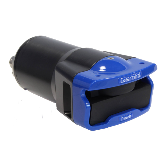
Gemini 720is Imaging Sonar 1. Introduction 1.1. General Overview The Gemini 720is is a 2D imaging sonar. It is a multibeam sonar, offering a 120° field of view with update rates of up to 30Hz giving rapid feedback to the user (hardware is capable of 30Hz, Seanet Pro is limited to 15Hz). -
Page 9: Software Version
Introduction Gemini 720is Imaging Sonar Caution Power should only be applied to the MAIN port of the Gemini. The AUX port, if fitted, provides a regulated power supply - please refer to Section 2.1, “Gemini 720is” for more information. 1.4. Software Version Note The instructions within this manual apply to the following software versions: •... -
Page 10: Technical Specification
Gemini 720is Imaging Sonar 2. Technical Specification 2.1. Gemini 720is All dimensions are in mm, not to scale Acoustic Operating Frequency 720kHz, CHIRP selectable Number of Channels Angular Resolution 1.0° acoustic, 0.25° effective Scanning Sector 120° Number of Beams Vertical Beamwidth 20°... -
Page 11: Hardware Installation & Configuration
Gemini 720is Imaging Sonar 3. Hardware Installation & Configuration Caution Although the sonar head is rugged, it should be handled with care, particularly the connector and receiver/transmitter elements. The plastic guard fitted to the unit will not be able to protect the sonar against significant impacts. 3.1. - Page 12 Hardware Installation & Configuration Gemini 720is Imaging Sonar Connector Maintenance Guidelines Mating surfaces should be lubricated with 3M Silicone Spray or equivalent, DO NOT GREASE. Connectors must be lubricated on a regular basis. Clean plugs and receptacles with soap and fresh water. Caution When attaching a connector make sure that both connector and socket are completely dry.
-
Page 13: Sonar Head Pin-Out Diagrams
Hardware Installation & Configuration Gemini 720is Imaging Sonar 3.3. Sonar Head Pin-Out Diagrams The following pin out diagrams details the appropriate connectors for each major variant of the Gemini 720is. 3.3.1. Single Seacon 5506-1508 connector S11108 (1000m) or S11109 (4000m) Gemini 720is fitted with a single Seacon 55 series connector using Ethernet communications only. -
Page 14: Single Schilling Seanet Connector
Hardware Installation & Configuration Gemini 720is Imaging Sonar Bulkhead view Function Ethernet RX+ Ethernet RX- DC + Ethernet Tx+ Ethernet Tx- DC Ground Chassis 3.3.3. Single Schilling SeaNet connector S11112 (4000m) only Gemini 720is fitted with a Schilling Seanet connector, using Ethernet communications. Bulkhead view Function DC +... -
Page 15: Single Subconn Fcr1508M Connector
Hardware Installation & Configuration Gemini 720is Imaging Sonar 3.3.5. Single SubConn FCR1508M connector S11532 (4000m) only Gemini 720is fitted with a single SubConn FCR1508M connector, using Ethernet communications. Bulkhead view Function Ethernet RX+ Ethernet RX- DC + Ethernet TX+ Ethernet TX- DC Ground CHASSIS 3.3.6. -
Page 16: Single Titan Impulse Mks(W)-307-Fcr Connector
Hardware Installation & Configuration Gemini 720is Imaging Sonar Bulkhead view Function Ethernet Rx+ Ethernet RX- Ethernet Tx+ DC + DC + Ethernet Tx- DC Ground DC Ground TTL Ground TTL In 3.3.8. Single Titan Impulse MKS(W)-307-FCR connector S11415 (1000m) only Gemini 720is fitted with a single Titan Impulse MKS(W)-307-FCR connector using VDSL communications. -
Page 17: Surface Adapter Pin-Out Diagrams
Hardware Installation & Configuration Gemini 720is Imaging Sonar MAIN MAIN Bulkhead Bulkhead Function Function view view Ethernet Rx+ Ethernet Rx+ Ethernet Rx- Ethernet Rx- Ethernet Tx+ 24V DC + DC + 0V DC Ethernet Tx+ Ethernet Tx- Ethernet Tx- DC Ground S11017 (1000m) or S11027 (4000m) Gemini 720is fitted with two Seacon 55 series connectors. -
Page 18: Ethernet Adapter
Hardware Installation & Configuration Gemini 720is Imaging Sonar 3.4.1. Ethernet Adapter Not to scale, dimensions in mm. Sonar Head Connector Function Diagram Photograph Ethernet RX+ Ethernet RX - Ethernet TX+ DC + DC + Ethernet TX - DC Ground DC Ground not connected not connected not connected... -
Page 19: Vdsl Adapter
Hardware Installation & Configuration Gemini 720is Imaging Sonar 3.4.2. VDSL Adapter Not to scale, dimensions in mm. Sonar Head Connector Function Diagram Photograph DC Ground DC + not connected VDSL + VDSL - not connected cable screen Souriau UTS7147S VDSL DC Connector Function Diagram Photograph... -
Page 20: An Example Ethernet Setup
Hardware Installation & Configuration Gemini 720is Imaging Sonar 3.5. An Example Ethernet Setup Test or bench setup for the Gemini Sonar system using Ethernet communications via the Ethernet adapter unit (Gemini 720is shown). Ethernet Adapter Computer CAT5 Patch Cable Gemini 720is Gemini PSU Blanking Ethernet / power test cable... -
Page 21: An Example Vdsl Setup
Hardware Installation & Configuration Gemini 720is Imaging Sonar 3.6. An Example VDSL Setup Test or bench setup for the Gemini Sonar system using VDSL communications via the VDSL adapter unit (Gemini 720is shown). VDSL Adapter Computer CAT5 Patch Cable Gemini 720is Gemini PSU Blanking VDSL / power test cable... -
Page 22: An Example Rov Setup
Hardware Installation & Configuration Gemini 720is Imaging Sonar 3.7. An Example ROV Setup An example of connections for an ROV, with the Gemini Sonar system using VDSL communications via the VDSL adapter unit (Gemini 720is shown). VDSL Adapter Computer power supply from vessel Gemini 720is Blanking... -
Page 23: Multiple Head Installation
Hardware Installation & Configuration Gemini 720is Imaging Sonar 3.8. Multiple Head Installation It is possible to control and display up to four Gemini heads from one computer using the Gemini software. In order to do this extra hardware will be required to connect the extra Gemini heads to the system as detailed: Using the Gemini The Ethernet Interface Box will output to a standard Ethernet... -
Page 24: Gemini Software Installation
Gemini 720is Imaging Sonar 4. Gemini Software Installation The Gemini head is supplied with software to control the functions of the sonar and to display the captured images. The software is supplied as an installer package which installs the software and a number of supporting files and documentation. Note The software is also available for download from www.tritech.co.uk... -
Page 25: Configuring The Gemini
Gemini Software Installation Gemini 720is Imaging Sonar Click on the Multibeam button and the following screen will display all the appropriate software packages for installation. Click on the appropriate installation option and then follow the onscreen prompts and instructions. Note Do not attempt to remove the CD-ROM from your computer during the installation process. -
Page 26: Check The Operation Of The Gemini
Gemini Software Installation Gemini 720is Imaging Sonar Note For instructions on setting the computer and Gemini IP address please refer to Appendix A, Setting the computer IP address in Windows® XP or Appendix B, Setting the computer IP address in Windows® 7 or Windows® 10 and Appendix C, Setting the Gemini Device IP Address in Gemini Software. -
Page 27: Gemini Software Operation
Gemini 720is Imaging Sonar 5. Gemini Software Operation Note To access the online help hover the mouse pointer over a control and press the F1 key. Note In order to communicate with a Gemini Imaging Sonar, the Gemini software must be set to run in Imager mode. -
Page 28: Online Button
Gemini Software Operation Gemini 720is Imaging Sonar On the lower left hand side of the screen are the range and gain controls for the sonar. On the lower right hand side of the screen are the indicators showing the pointer position within the display area. -
Page 29: Record Button
Gemini Software Operation Gemini 720is Imaging Sonar If the head is not able to connect due to being on a different network or having different network settings the following will be displayed: Note To correctly set up the network refer to Appendix B, Setting the computer IP address in Windows®... - Page 30 Gemini Software Operation Gemini 720is Imaging Sonar From left to right they are Play, Stop, Repeat and Load. The controls that are enabled will depend on what the software is doing, for example, it is not possible to do anything with the player controls whilst the software is acquiring data from the Gemini head, nor is it possible to open a file whilst another file is already playing.
-
Page 31: Capture Screen
Gemini Software Operation Gemini 720is Imaging Sonar Frame Number and Speed Control The Frame control is a slider bar which allows the user to move quickly around the file that has been loaded. The number at the right hand end is the currently displayed frame number from the file. -
Page 32: Record Video
Gemini Software Operation Gemini 720is Imaging Sonar 5.1.6. Record Video The Record Video button is used to capture replayed Gemini data as a video file. Video capture is only available when a file is being replayed and cannot be performed on live Gemini data. When a file has been loaded and the playback of the file has been paused or stopped, the Record Video button will be enabled. -
Page 33: Chirp Button
Gemini Software Operation Gemini 720is Imaging Sonar Zoom box example with Gemini Sonar data In order for the Acoustic Zoom window to show data during replay, the Zoom button must have been enabled with a CHIRP enabled Gemini unit during the initial recording of the file. 5.1.8. -
Page 34: Rotate Image
Gemini Software Operation Gemini 720is Imaging Sonar 5.1.11. Rotate Image The Rotate Image button turns the image from the sonar by 90°. The Invert Display and Flip Image controls will still affect the image displayed on screen. Rotate Image example with Gemini Sonar data 5.1.12. -
Page 35: Filter Selector
Gemini Software Operation Gemini 720is Imaging Sonar The zoom window positions itself to either the left hand side or the right hand side of the screen so that it does not obscure the Gemini data. The magnification level of the window is changed by using the mouse wheel, or by using the + and –... -
Page 36: Gain Control
Gemini Software Operation Gemini 720is Imaging Sonar 5.1.17. Gain Control The Gain slider at the bottom left hand side of the display is used to change the gain level being used by the Gemini head, and is expressed as a percentage between 0 (no gain being applied) and 100 (full gain being applied). -
Page 37: Measurements
Gemini Software Operation Gemini 720is Imaging Sonar Drag the mouse to move the handle to the desired location and then release the mouse button. There will be a short delay (depending on network bandwidth) while the profiler is updated with the new swathe size. It is possible to adjust the swathe size using the keyboard by pressing the b or g keys. -
Page 38: Advanced Screen
Gemini Software Operation Gemini 720is Imaging Sonar At the end of this period the sonar will enter a power saving mode to reduce the heat build up within the unit. The software will still display information about the sonar during this power saving mode, but the sonar will not re-enable it's ability to transmit until the Online button has been toggled off then on. -
Page 39: System Data
Gemini Software Operation Gemini 720is Imaging Sonar The Advanced screen shows more details about the Gemini system, and allows certain options in the software to be configured. The screen is split into three areas: the User area, which has been previously described in Section 5.1.1, “Overview”; the lower left area of the screen contains the System Data tabs;... - Page 40 Gemini Software Operation Gemini 720is Imaging Sonar When changing this setting, the user will be prompted to allow the software to restart. Once the software restarts, all Imager settings and relevant options will be available. Sonar Selection The Sonar ID of the Gemini Sonar is used to determine which sonar will be used as the source of images displayed by the software.
- Page 41 Gemini Software Operation Gemini 720is Imaging Sonar The Enable Compression button toggles the compression when clicked (black background to the button means compression is off, blue background means compression is on). The Compression control sets the level applied by the run length encoding; returns below this intensity percentage will be set to zero.
-
Page 42: Application Settings
Gemini Software Operation Gemini 720is Imaging Sonar Note Compression is applied before the software receives the sonar data and therefore compression cannot be applied to data that has already been recorded. Conversely, recorded data that has been compressed cannot be uncompressed. Acquisition Speed Acquisition speed is another mechanism available for reducing the sonar data rate and required bandwidth. - Page 43 Gemini Software Operation Gemini 720is Imaging Sonar Measurement The Measurement control selects between Measurement Tool annotation options that display distance in the Gemini data view. The user may select the measurement to be shown in polar coordinates, Cartesian coordinates, or no annotation displayed. For more information on the Measurement Tool see Section 5.1.21, “Measurements”.
-
Page 44: Filter Settings
Gemini Software Operation Gemini 720is Imaging Sonar The list contains the following options: commonly used screen resolutions (i.e. 1920x1080) and a Screen (x) option, which is the current monitor resolution. Note Recording large videos may fail on systems with insufficient memory. If videos are not written correctly or have no frames then decrease the resolution before recording. -
Page 45: Device Network Settings
Gemini Software Operation Gemini 720is Imaging Sonar The Movement filter highlights the changes between images and filters out static returns. The Movement control sets how much background (i.e. non-moving data) is removed from the image. With the Movement control set at maximum, the movement filter removes all of the background and so the display only shows targets that are moving between images. -
Page 46: Distance Marker
Gemini Software Operation Gemini 720is Imaging Sonar 5.2.6. Distance Marker The Distance Marker provides a mechanism for measuring the distance between two points in the Gemini data view. This is similar to the Measurement Tool but provides additional options that allow it to be used as a more permanent measurement. Enable the feature by clicking the Enable Distance Marker button. -
Page 47: Target Tracking
Gemini Software Operation Gemini 720is Imaging Sonar The Distance Marker range/ Y coordinate may be updated from an external sensor. Enabling the Distance Range from Sensor button will update the value whenever a configured sensor message is received. See Appendix E, Gemini Software String Decode for the appropriate Marker Range decode options. - Page 48 Gemini Software Operation Gemini 720is Imaging Sonar Click + Track In order to track a single target, the Track Single Target option can be selected from the Targets menu. This restricts the user to select one target at a time and has the benefit of displaying the target position.
- Page 49 Gemini Software Operation Gemini 720is Imaging Sonar Detect + Track In order to track objects effectively, the various settings need to be optimised. Target Size This is the estimated size of target that is to be tracked. Maximum Targets This sets an upper limit of the number of targets that will be considered for tracking. Setting this to a large number will increase the load on the computer CPU and may cause the Gemini software to slow down.
-
Page 50: Serial Data Input
Gemini Software Operation Gemini 720is Imaging Sonar Once enabled, potential targets will be highlighted in the appropriate colour, green in this instance. To track one or more targets, place the mouse cursor over it and right click on it. A small cross will appear in each target selected. -
Page 51: Sonars & Sensors
Gemini Software Operation Gemini 720is Imaging Sonar Selecting Enabled for either Gemini Hub or COM Ports will alter the tab options in the bottom left of the screen. If both are disabled there will be no tabs visible and the status area will only display information about connected Gemini heads. -
Page 52: Gemini Hub
Gemini Software Operation Gemini 720is Imaging Sonar 5.3.2. Gemini Hub Hubs Tab The Hubs tab shows the status information from any connected Gemini Hubs. Hub Setup Tab The Hub Setup tab allows configuration of the serial ports on the rear of the Gemini Hub to allow RS232 data to pass through to the Gemini software from external sensors. -
Page 53: Com Ports
Gemini Software Operation Gemini 720is Imaging Sonar String The incoming data string, check this against the chosen Decode if the data indicator is red. Note The data age status indicator will show the status of each port. A grey indicator means no data is present, red is for an incorrect data string, yellow indicates an incomplete data string and green is for normal operation. -
Page 54: Aux Power
Gemini Software Operation Gemini 720is Imaging Sonar Note The data age status indicator will show the status of each port. A grey indicator means no data is present, red is for an incorrect data string, yellow indicates an incomplete data string and green is for normal operation. Sonar Ports The Sonar Ports tab controls the two serial channels available on each Gemini 720is unit that is connected. -
Page 55: Gemini Firmware Updates
Gemini Software Operation Gemini 720is Imaging Sonar Caution As the Aux port is powered by an internal regulator, the maximum power limit should never be exceeded. Doing so will damage the Gemini 720is. Note The Aux Power control will only affect Gemini 720is units that have serial based Aux ports. -
Page 56: Multiple Head Operation
Gemini Software Operation Gemini 720is Imaging Sonar The firmware update process will start. It is a two step process and both must be completed in order for the firmware to be completely upgraded. It is important that power to the Gemini is not disconnected at any point during the upgrade process... - Page 57 Gemini Software Operation Gemini 720is Imaging Sonar The first time the number of heads is altered the sonar display will place the sonars side-by- side in a line. Any subsequent alterations to the position or rotation of each sonar image is stored and recalled when the Gemini software is restarted.
- Page 58 Gemini Software Operation Gemini 720is Imaging Sonar Note Turning off the range lines and text can improve the display. In this case, sonar 1 is looking forward while 2 and 3 are looking aft. There is no overlap and each sonar is displaying a full 120° arc. Overlapping sonars is also possible and any images generated will be a combination of echoes from both heads: Document: 0703-SOM-00002, Issue: 7...
-
Page 59: Offline Mode
Gemini Software Operation Gemini 720is Imaging Sonar 5.6. Offline Mode If for some reason when the software is started it cannot initialise communications with the Sonar (for example if another instance of the software already running) the following warning will be displayed: The software will then open with a cut down user interface which will allow the replay of data which have already been recorded, but all the controls associated with the Gemini Sonar will be removed. -
Page 60: Keyboard Shortcuts
Gemini Software Operation Gemini 720is Imaging Sonar 1. Shut down the Gemini software. 2. Delete (or rename) the C:\GeminiData\Settings\Gemini.xml file. 3. Start the Gemini software. 5.9. Keyboard Shortcuts A number of keyboard shortcuts are available for commonly used activities. Toggle Logging of data Ctrl F Capture the screen to file Increase gain... -
Page 61: Seanet Pro Installation
Gemini 720is Imaging Sonar 6. Seanet Pro Installation 6.1. System requirements Minimum Recommended Processor 2GHz 2GHz dual core Graphics 3D hardware accelerated graphics card. Display 1280x1024 (32bit colour) 1600x1200 (32bit colour) Disk space Install is 20MB, greater than 160GB recommended for log files Networking 100Mbit·s (fast Ethernet) - Page 62 Seanet Pro Installation Gemini 720is Imaging Sonar Click on the appropriate installation option and then follow the onscreen prompts and instructions. • Seanet Pro using AIF Card - select this option if you are using a SCUv4, or PC equiped with a PCI AIF card. •...
- Page 63 Seanet Pro Installation Gemini 720is Imaging Sonar Note In order to correctly run the Gemini head on a SCU the SCUv5, or later, is required. Contact Tritech International Ltd for more details of the SCUv5. Document: 0703-SOM-00002, Issue: 7 © Tritech International Ltd.
-
Page 64: Seanet Pro Operation
Gemini 720is Imaging Sonar 7. Seanet Pro Operation Note This section details the aspects of Seanet Pro that are specific to the Gemini Sonar. For more general information (particularly if integrating with other devices) please see the Seanet Pro Software Manual which is available online www.tritech.co.uk Before starting operations, run Seanet Setup to verify that the Gemini LAN is enabled and any connected devices, including the Gemini sonar, are detected. - Page 65 Seanet Pro Operation Gemini 720is Imaging Sonar Modify Network Address The Sonar IP Address and Subnet Mask should be in the same range as the Computer IP Address and Subnet settings. To program a different Sonar IP Address and/or Subnet Mask into the selected Gemini Sonar, change the values in this panel and then click ‘OK’...
- Page 66 Seanet Pro Operation Gemini 720is Imaging Sonar Click on Setup in the Action column to open the Gemini Cfg Setup dialog. Gemini Cfg Setup Velocimeter Mode Set to 'Auto' to apply the in-built velocimeter speed of sound calculation to the sonar data. Set to 'Manual' to revert to a fixed speed of sound.
-
Page 67: Gemini Sonar Application
Seanet Pro Operation Gemini 720is Imaging Sonar period of rate adaption, the top-left of the Sonar screen will indicate the status text Acquiring… (in red text). Once all changes have been made, click on OK to update the Gemini. 7.2. Gemini Sonar Application Note Refer to the Seanet Pro Software Manual manual for a comprehensive description of the menu bar, buttons, status bar and general features. - Page 68 Seanet Pro Operation Gemini 720is Imaging Sonar 1. Application Tools Clicking on the tools icon on the left of the Sonar Settings Bar will open the Application Tools menu 2. Application On, Off, Pause This doubles as a pause button and a status indicator. Clicking on the button will pause the signals from sonar to Seanet Pro and pause the screen from refreshing.
-
Page 69: Application Tools
Seanet Pro Operation Gemini 720is Imaging Sonar 7.2.2. Application Tools Click on the Tools icon on the left of the Sonar Settings Bar to open the popup menu which includes all the Application Tools for the Gemini Sonar. Note The popup menu can also be accessed by a right mouse button click on the Sonar display. - Page 70 Seanet Pro Operation Gemini 720is Imaging Sonar Figure 7.3. When both markers are dropped on the display, a line will be drawn which connects them. The ‘Delta’ Range and Bearing at the bottom of the panel indicates separation and angle between both Markers.
- Page 71 Seanet Pro Operation Gemini 720is Imaging Sonar Installation Figure 7.5. This configures the location of the Sonar in the real world and enables the Geo-referencing of sonar targets on the sonar display. From Fixed Position If there is no GPS input, select this option and input the Sonar position in Latitude and Longitude co-ordinates (DegMin or DegMinSec format).
- Page 72 Seanet Pro Operation Gemini 720is Imaging Sonar connected through a COM port on the SCU or PC, or if a USBL system is in use then select Ship/USBL Compass. If the sonar is mounted to an ROV and both the ROV and support vessel have a compass it is possible to switch to the ROV compass by selecting Sub/ROV Compass.
- Page 73 Seanet Pro Operation Gemini 720is Imaging Sonar If more than one sensor is available for selection this should be performed in the Installation dialog. If an offset is required it can be entered here and the compass can be corrected for displacement of magnetic against True North.
- Page 74 Seanet Pro Operation Gemini 720is Imaging Sonar • Auto - This setting will allow the Gemini Sonar to control the CHIRP function based upon the range setting within Seanet Pro. Typically CHIRP will be switched On for ranges greater than 3M Velocity of Sound This panel displays the Velocity of Sound value being used by the Gemini Sonar.
- Page 75 Seanet Pro Operation Gemini 720is Imaging Sonar When selected, a Zoom box will appear on screen and is movable by pressing and holding the left mouse button and then dragging to the desired location. The area chosen by the Zoom box will be over sampled by the Gemini (for the Digital zoom option) in order to provide a higher resolution picture at that point.
-
Page 76: Outputting Data Via Remv4
Seanet Pro Operation Gemini 720is Imaging Sonar 7.3. Outputting data via REMV4 With the Gemini 720is setup to process an incoming serial data stream (see Section 7.1, “Seanet Setup for Gemini” for details) the incoming data can be set to output to external software packages using the REMV4 software. -
Page 77: Maintenance
Gemini 720is Imaging Sonar 8. Maintenance 8.1. After using Sonar Make sure that after using the sonar head that it is washed down with fresh water and check the unit for any signs of obvious damage. Pay particular attention to the transducer head and free any organic matter which has become trapped. - Page 78 Maintenance Gemini 720is Imaging Sonar Using a M3 Allen key, unscrew the top and bottom retention screws from the cover. Once both screws have been removed, gently pull the cover away from the main body of the sonar. The area surrounding the transmitter and receiver can now be visually inspected for any salt deposits and cleaned as appropriate.
-
Page 79: Troubleshooting
Gemini 720is Imaging Sonar 9. Troubleshooting The software reports that no sonars are detected VDSL System – Check the VDSL link light on the Gemini Hub (note that it may take up to 1 minute to establish a stable VDSL link). If there is no VDSL link light then check all cabling between Gemini Hub and the sonar and verify that the sonar is powered correctly with appropriate voltage at the sonar. - Page 80 Troubleshooting Gemini 720is Imaging Sonar Note The sonar will only respond to ping requests from IP addresses on the same subnet as the sonar. Some firewalls have been known to cause this issue. To view the computers routing table type "route print" from the command line. Update rate is slow and there are sometimes large gaps between pings VDSL System - The VDSL link is susceptible to electrical noise induced by turning other...
-
Page 81: Setting The Computer Ip Address In Windows® Xp
Gemini 720is Imaging Sonar Appendix A. Setting the computer IP address in Windows® XP The following instructions apply to a computer running Windows® XP, though the sequence for other operating systems will be similar. If the computer is connected to a network already, disconnect it from that network. From the Start Menu select Control Panel. - Page 82 Setting the computer IP address in Windows® XP Gemini 720is Imaging Sonar Make a note of the settings as currently used by the computer; these will be needed to restore the computer to any existing network. Refer to the appropriate section of this manual for the correct IP address to use.
-
Page 83: Setting The Computer Ip Address In Windows® 7 Or Windows® 10
Gemini 720is Imaging Sonar Appendix B. Setting the computer IP address in Windows® 7 or Windows® 10 The following instructions apply to a computer running Windows® 7 or Windows® 10, though the sequence for other operating systems will be similar. All screenshots are from a Windows®... - Page 84 Setting the computer IP address in Windows® 7 or Windows® 10 Gemini 720is Imaging Sonar A list of attached network devices should now present itself. Find the one which the Gemini head is to be connected to and double-click on it. The Local Area Connection Properties dialog should be displayed.
-
Page 85: Setting The Gemini Device Ip Address In Gemini Software
Gemini 720is Imaging Sonar Appendix C. Setting the Gemini Device IP Address in Gemini Software These instructions are applicable to any Gemini device. For a Sonar or Enter the ID into the Sonar box of the Advanced Configuration options Profiler (upper right hand side of the screen). -
Page 86: Setting The Gemini Head Ip Address In Seanet Pro
Gemini 720is Imaging Sonar Appendix D. Setting the Gemini Head IP Address in Seanet Pro Run Seanet Setup and click on Gemini LAN in the Setup menu. This will open the Gemini LAN Setup dialog. Ensure that the Gemini is connected directly to the computer. In the Selected Sonar drop-down control, ensure that the correct Gemini is selected. - Page 87 Setting the Gemini Head IP Address in Seanet Pro Gemini 720is Imaging Sonar IP Address for details of how to do this). Once communication has been re-established the following screen shows the sonar is connected: Returning to Gemini LAN from the Setup menu should confirm that the changes have been made successfully.
-
Page 88: Gemini Software String Decode
Gemini 720is Imaging Sonar Appendix E. Gemini Software String Decode The Gemini Software is capable of handling input from various different types of sensors using the following standard strings: Depth strings Name Description Format/Examples Digi Parascientific Digiquartz 000.0 (depth sensor) SonDepth Depth $SONDEP... - Page 89 Gemini Software String Decode Gemini 720is Imaging Sonar Heading, Position and Time strings Name Description Format/Examples CDL1 Heading, Pitch, Roll Haaa.aP+ccc.ccR+eee.eeT... GPGGA GPS position $GPGGA... GPGGA ZDA GPS position and UTC time $GPGGA... $GPZDA... $GPZDA UTC Time $GPZDA... HEHDT Heading $HEHDT...
-
Page 90: Gemini Software String Encode
Gemini 720is Imaging Sonar Appendix F. Gemini Software String Encode The Gemini Software is capable of outputting different data strings depending on the requirement of the user: Target tracking strings Name Description Format/Examples PTRITAR Basic target tracking output string $PTRITAR, DDMMYYYY, HHMMSS, (Gemini 720i / 720id / NBI) 1, 0.0, 0.0, CS PTRITR1... -
Page 91: Glossary
Gemini 720is Imaging Sonar Glossary 2 Dimensional ASCII American Standard Code for Information Interchange - a character encoding scheme originally based on the English alphabet. Audio Video Interleave - a video format introduced by Microsoft A raster graphics image file format used to store bitmap digital images. CAT5e Category 5 enhanced - a standard specification for Ethernet cables. - Page 92 Glossary Gemini 720is Imaging Sonar Multibeam A sonar which forms multiple "beams" of sound so it can update in real time and does not have to perform a full scan like a traditional sonar. Personal Computer The standard filename extension for Portable Network Graphics - a bitmapped image format employing lossless compression.
Need help?
Do you have a question about the Tritech Gemini 720is and is the answer not in the manual?
Questions and answers