
Subscribe to Our Youtube Channel
Related Manuals for Moog Tritech Super SeaKing V7


Summary of Contents for Moog Tritech Super SeaKing V7
- Page 1 Super SeaKing V7 Sonar Product Manual Document No 0721-SOM-00001-01 A Moog Inc. Company Outstanding Performance in Underwater Technology...
- Page 2 This page has deliberately been left blank.
- Page 3 Westhill, Aberdeenshire AB32 6JL, UK Telephone +44(0)1224 744 111 Email tritech-support@moog.com Website www.moog.com/tritech Prior to contacting Tritech International Ltd please ensure that the following information is available: The Serial Numbers of the product and any Tritech International Ltd equipment connected directly or indirectly to it...
- Page 4 Warning Symbols Throughout this manual the following symbols may be used where applicable to denote any particular hazards or areas which should be given special attention: Note This symbol highlights anything which would be of particular interest to the reader or provides extra information outside of the current topic. Important When this is shown there is potential to cause harm to the device due to static discharge.
-
Page 5: Table Of Contents
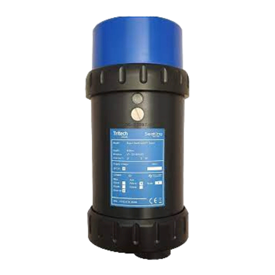
Table of Contents Contents Installations Hardware Installation ............8 Powering the Sonar ............. 9 Electrical Connections ............9 Communications Configurations ......10 Ground fault Monitoring ..........10 Wiring Diagrams ..............11 Tritech V7 Connector ............12 SeaKing Magnetic Reset ..........12 Software Installation System Requirements ............13 Genesis Software Installation........13 Software Overview .............13 Windows Setup ..............14... - Page 6 1. Overview Overview The V7 Super SeaKing DST mechanical scanning sonar offers enhanced performance and the option of Ethernet communication for high speed scanning over short ranges. Retaining dual frequency capability, the Super SeaKing DST can achieve 300m range at 325kHz, with increased image intensity and with improved mid-water target discrimination capability at 675kHz.
- Page 7 Technical Specifications 4000m Aluminium Housing Dimensions in millimetres. Super Seaking V7 Super Seaking V7 Super Seaking V7 Physical Properties (Aluminium) (Titanium) (Titanium) Depth Ratings 4000m 4000m 6800m Weight in air 3.0kg 4.1kg 4.8kg Weight in Water 1.4kg 2.5kg 2.9kg Temperature Ratings Operating -10°C to 35°C, Storage -20°C to 50°C SeaKing Acoustic Low Frequency 325kHz...
-
Page 8: Installations
2. Installations Hardware Installation The sonar should be mounted using suitable pipe clamps, or similar to firmly secure it to the vehicle. Tritech recommends the use of 3mm insulating rubber spacers to aid grip and prevent damage to the anodised coating. It’s recommended, during installation, that the Sonar be positioned so it has an unobstructed view of the intended scan area, while also avoiding prop-wash from thrusters. -
Page 9: Powering The Sonar
Powering the Sonar The Super Seaking V7 Series systems are designed to operate from a smoothed DC power supply. If using a rectified transformer PSU, the output of the PSU must have a filter capacitor of not less than 470μF, for each unit being powered. -
Page 10: Communications Configurations
Communications Configurations The V7 is a direct replacement for a V6 sonar, with the exception of customers requiring Ethernet capability. This will require either a proprietary Tritech V7 connector or a compatible connector and cable harness. ARCNET and Serial comms protocols are still supported.. Super Seaking V7 Sonar can be configured as Ethernet and Serial RS232/485 or as ARCNET and Serial RS232/485 communication protocols. -
Page 11: Wiring Diagrams
Wiring Diagrams The wiring diagrams below refer to the V7 Tritech connector on the main port and show the standard Tritech connector wiring on the Aux port. Other connector options are available upon request, please contact our sales team for full details. WARNING Application of reverse supply voltage to the unit or supply voltage across any of the communication connections may lead to equipment damage not covered... -
Page 12: Tritech V7 Connector
Tritech V7 Connector The V7 cable connector has the addition of the screen contact in the outer ring of the connector. This makes contact with the chassis ground of the system which is required when using Ethernet Comms. When using ARCNET and Serial Communications systems, standard cables are compatible. -
Page 13: Software Installation
Once installed, you can launch the application from the desktop icon or from the Start menu in windows. Updates Download the latest software versions from www.moog.com/tritech Tritech International Ltd continually develop our software so it is recommended to check the website for updates regularly. -
Page 14: Windows Setup
Windows Setup Ethernet Protocol Settings The Ethernet adapter needs to be setup on the host PC to be in the same IP address range as the sensor being attached. Using Ethernet comms, allows multiple sensors to be integrated using standard networking equipment. The TCP/IPv4 network configuration of the host network adapter (PC, SCU or similar) should be set to an IP address of 192.168.2.xxx with a subnet mask 255.255.255.0. -
Page 15: Genesis Comms Setup
4. Genesis Comms Setup The Genesis software package from Tritech allows the control, configuration and display of Tritech imaging and survey sensor data from within a single software environment. The Following section will guide you through the process of setting up your system to communicate with your chosen devices. Main GUI window Devices are automatically added into Genesis as they are connected to the system via the Ethernet or Tritech... -
Page 16: Adding A Serial Device
Adding a Serial Device To add a serial device to your system, the com port settings must configured within Genesis. The following section outlines the process of adding devices to your serial network. Clicking on the “Devices” button in the top right of the Genesis GUI will bring up the Device configuration window with a list of all Genesis compatible Tritech Devices. -
Page 17: Modifying Ip Addresses
Modifying IP Addresses To avoid IP conflicts in your system, each device must have a different IP address to allow them to communicate with Genesis. When running multiple devices it may be necessary to change the IP address of a connected device. To do this, ensure the device is online and select the device status icon in the toolbar to show its properties... -
Page 18: Arcnet Termination
Appendix. Appendix 1. ARCNET Termination Depending on the cable length the ARCNET communication link requires a termination resistor to be installed at each end of the umbilical cable. Normally this is supplied fitted within the ARCNET cable DA-15 or within the SCU/SeaHub at the surface and is left for the user to fit at the sub-sea end in a convenient junction box or by use of a special waterblock.
Need help?
Do you have a question about the Tritech Super SeaKing V7 and is the answer not in the manual?
Questions and answers