UNI-T UT322 Operating Manual
Hide thumbs
Also See for UT322:
- Operating manual (37 pages) ,
- Operating manual (2 pages) ,
- Operating manual (2 pages)
Table of Contents
Advertisement
Quick Links
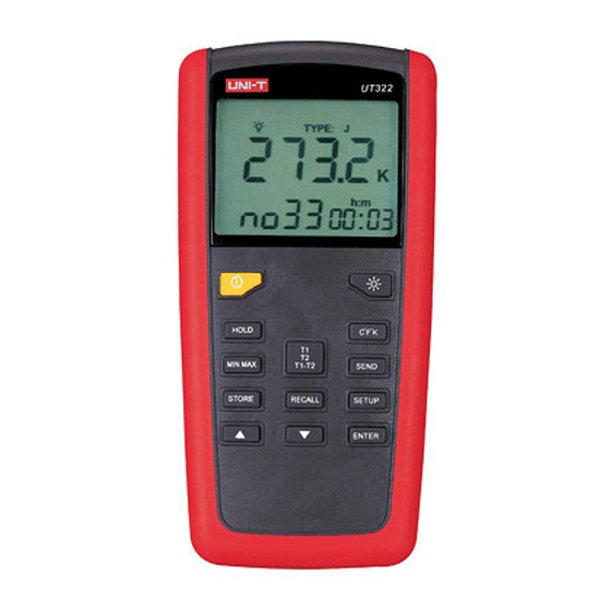
Model UT321/322/323/325: OPERATING MANUAL
Table of Contents
Entering and Exiting Setup
Changing the Logging Interval
Changing the Thermocouple Type
Changing the Offset (T1)
Changing the Offset (T2)
Changing the Line Frequency
Setting the Time
Setting the Low Limit Alarm (Lo)
Setting the High Limit Alarm (Hi)
1
Page
4
7
8
10
12
16
16
17
17
18
18
18
19
19
19
20
21
Advertisement
Table of Contents


Need help?
Do you have a question about the UT322 and is the answer not in the manual?
Questions and answers