
Subscribe to Our Youtube Channel
Related Manuals for Samsung AM NNN Series


Summary of Contents for Samsung AM NNN Series
- Page 1 Air conditioner User manual AM***NNN*EH*** • Thank you for purchasing this Samsung air conditioner. • Before operating this unit, please read this user manual carefully and retain it for future reference.
-
Page 2: Table Of Contents
Business users should contact their supplier and check the terms and conditions of the purchase contract. This product and its electronic accessories should not be mixed with other commercial wastes for disposal. For information on Samsung’s environmental commitments and product-specific regulatory obligations, e.g. REACH, WEEE, Batteries, visit: www.samsung.com/uk/aboutsamsung/sustainability/environment/our-commitment/data/... -
Page 3: Safety Information
If you have any questions, call your nearest contact centre or find help and information online at www.samsung.com. WARNING Hazards or unsafe practices that may result in severe personal injury or death. - Page 4 Safety Information The installation of this appliance must be performed by a qualified technician or service company. • Failing to do so may result in electric shock, fire, explosion, problems with the product, or injury. Install a switch and circuit breaker dedicated to the air conditioner. •...
- Page 5 CAUTION Install your appliance on a level and hard floor that can support its weight. • Failing to do so may result in abnormal vibrations, noise, or problems with the product. Install the drain hose properly so that water is drained correctly. •...
- Page 6 Safety Information FOR USING WARNING If the appliance is flooded, please contact your nearest service centre. • Failing to do so may result in electric shock or fire. If the appliance generates a strange noise, a burning smell or smoke, unplug the power plug immediately and contact your nearest service centre.
- Page 7 After unpacking the air conditioner, keep all packaging materials well out of the reach of children, as packaging materials can be dangerous to children. • If a child places a bag over its head, it may result in suffocation. Do not touch the front panel with your hands or fingers during the heating operation.
- Page 8 Safety Information CAUTION Do not place objects or devices under the indoor unit. • Water dripping from the indoor unit may result in fire or property damage. Check that the installation frame of the outdoor unit is not broken at least once a year.
- Page 9 This appliance is not intended for use by persons (including children) with reduced physical, sensory or mental capabilities, or lack of experience and knowledge, unless they have been given supervision or instruction concerning use of the appliance by a person responsible for their safety. Children should be supervised to ensure that they do not play with the appliance.
-
Page 10: At A Glance
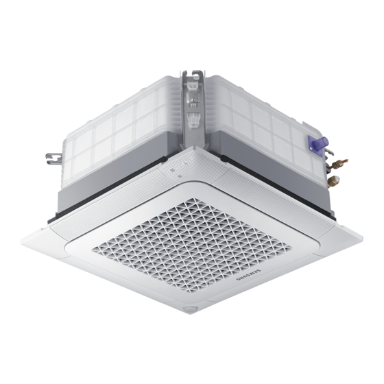
Indoor Unit Overview The indoor unit and its display may look slightly different from the illustration shown below, depending on the model and the panel type. 01 Display Indication Function On/Off operation indicator Removing frost indicator Timer indicator Filter cleaning indicator Remote control sensor 02 Air flow blade/Air outlet (inside) / Wind-Free panel... -
Page 11: Operation Features
Operation Features Operating temperature and humidity When using the air conditioner follow the operating temperature and humidity ranges. Mode Indoor temperature Outdoor temperature Indoor humidity Cool mode 18~32 °C Depending on the outdoor Dry mode 80% or less unit specification Heat mode 30 °C or less CAUTION... -
Page 12: Cleaning And Maintenance
Cleaning and Maintaining Before cleaning the indoor unit, be sure to turn off the auxiliary power switch. Cleaning the indoor unit exterior Wipe the surface of the unit with a slightly wet or dry cloth when needed. Wipe off dirt of odd- shaped areas by using a soft brush. - Page 13 NOTE • The hooks are located on both sides of the front grill with the Samsung logo. Pull out the air filter from the indoor unit. 2 Cleaning the air filter Clean the air filter with a vacuum cleaner or soft brush.
- Page 14 Cleaning and Maintaining 3 Reassembling the air filter CAUTION • If the indoor unit is used without the air filter, the indoor unit may be damaged due to dust. 4 Resetting the air filter After cleaning and reassembling the air filter, be sure to reset the filter-cleaning reminder as follows: •...
- Page 15 Periodical maintenance Requires qualified Unit Maintenance item Interval technicians Clean the air filter. At least once a month Clean the condensate drain pan. Once a year Required Indoor Clean up the heat exchange. Once a year Required unit Clean the condensate drain pipe. Once every 4 months Required Replace the remote control batteries.
- Page 16 Cleaning and Maintaining Troubleshooting Refer to the following chart if the air conditioner operates abnormally. This may save time and unnecessary expense. Problem Solution The air conditioner • Because of the protective mechanism, the appliance does not start does not operate operating immediately to keep the unit from overloading.
- Page 17 Problem Solution The wired remote • Check whether the indicator is displayed at the bottom right of the control does not remote control display. In this case, turn off both the air conditioner and operate. the auxiliary power switch, and then contact a service centre. The air conditioner is not turned on or •...
- Page 18 Cleaning and Maintaining Problem Solution • Close the windows and doors to maximize the cooling and heating efficiencies. • If the Cool mode is stopped and then started immediately, cool air comes out after about 3 minutes to protect the compressor of the outdoor unit. The air is not cool or warm enough.
-
Page 19: Technical Specifications
Technical specifications Type Model Net weight (kg) Net dimension (W x D X H) (mm) AM015NNNDEH* 11.7 575 x 575 x 250 AM022NNNDEH* 575 x 575 x 250 AM028NNNDEH* 575 x 575 x 250 Indoor unit AM036NNNDEH* 575 x 575 x 250 AM045NNNDEH* 575 x 575 x 250 AM056NNNDEH*... -
Page 20: Installation Procedure
Installation Procedure Step 1 Installing the indoor unit CAUTION When deciding on the location of the air conditioner the • Make sure that the ceiling is strong enough to support following restrictions must be taken into account. the weight of the indoor unit. Before hanging the unit, test the strength of each attached suspension bolt. - Page 21 Step 3 Insulating the refrigerant pipes 7 Adjust the unit to the appropriate position, taking into account the installation area for the front panel. Once you have checked that there are no leaks in the • Place the pattern sheet on the indoor unit. system, you can insulate the piping and hose.
- Page 22 Installation Procedure Installation Procedure CAUTION Insulation Type (Heating/Cooling) • Must fit tightly against body without any gap. Pipe size Standard High humidity Pipe Remarks (mm) [30°C, 85%] [30°C, over 85%] • Make sure that all refrigerant connection must be accessible for easy maintenance and detachment. EPDM, NBR •...
- Page 23 Step 4 Installing the drain hose and • Install air ventilation to drain condensation smoothly. drain pipe Air ventilation 1 Push the supplied drain hose as far as possible over the drain socket. 2 Tighten the metal clamp as shown in the picture. Ceiling •...
- Page 24 Installation Procedure • Install horizontally. • Max. allowable bending angle. Be horizontal Indoor unit Max. 30˚ Indoor unit Flexible hose NOTE • Max. allowable axis gap. • If a concentrated drain pipe is installed, refer to the figure below. Indoor unit Max.
- Page 25 Step 5 Connecting the power and • To protect the product from water and possible shock, you should keep the power and the communication communication cables cables of the indoor and outdoor units in the iron pipe. • Connect the power cable to the auxiliary circuit breaker (ELCB, MCCB, ELB).
- Page 26 Installation Procedure Selecting the crimping terminal lug 1 Select the crimping terminal lug based on the norminal dimension of the power cable. 2 Cover the connection part of the power cable and crimping terminal lug to insulate it. Silver solder Norminal Norminal dimensions...
- Page 27 Specifications of the terminal blocks 2 Decide the power cable specification and maximum length within 10% voltage drop among indoor units. (Unit: mm) Coef×35.6×Lk × Communication: M3.5 screw AC power: M4 screw < 10% of input voltage[V] ∑ ( 1000×Ak NOTE •...
- Page 28 Installation Procedure and then insert them again. b While holding down the (High Temp) and SEG7 SEG8 SEG9 SEG10 SEG11 SEG12 (Low Temp) buttons simultaneously, insert the batteries into the remote control. c Make sure that you are entered to the mode for SEG13 SEG14 SEG15...
- Page 29 Steps Remote control display 2 Press the (Mode) button. Cool and On appear on the remote control display. 3 Set the SEG4 and SEG5 values: a Set the SEG4 value by pressing the (Low Fan) button repeatedly until the value you want to set appears on the remote control display. SEG4 b Set the SEG5 value by pressing the (High Fan) button repeatedly until the...
- Page 30 Installation Procedure Steps Remote control display b Set the SEG10 value by pressing the (High Fan) button repeatedly until the value you want to set appears on the remote control display. When you press the (Low Fan) or (High Fan) button, values appear in the following order: SEG10 8 Press the...
- Page 31 Steps Remote control display 13 Set the SEG16 and SEG17 values: a Set the SEG16 value by pressing the (Low Fan) button repeatedly until the value you want to set appears on the remote control display. SEG16 b Set the SEG17 value by pressing the (High Fan) button repeatedly until the value you want to set appears on the remote control display.
- Page 32 Installation Procedure Steps Remote control display 18 Press the (Mode) button. Heat and Off appear on the remote control display. 19 Set the SEG23 and SEG24 values: a Set the SEG23 value by pressing the (Low Fan) button repeatedly until the value you want to set appears on the remote control display.
- Page 33 Setting the indoor unit addresses (MAIN/RMC/ 3 Set an address (MAIN/RMC/MCU port) for each indoor MCU) unit using the remote control, according to your air conditioning system plan. 1 Make sure that the power is supplied to the indoor • The indoor unit addresses (MAIN/RMC/MCU port) unit.
- Page 34 Installation Procedure Option SEG13 SEG14 SEG15 SEG16 SEG17 SEG18 Setting MCU PORT 10-digit of MCU Function Page 1-digit of MCU MCU PORT address address address Indication Details Indication Details Indication Details Indication Details Indication Details No MCU PORT Indication PORT and details 10-digit 1-digit...
- Page 35 Installation options for the 02 series SEG1 SEG2 SEG3 SEG4 SEG5 SEG6 Use of external room temperature FAN RPM Evaporator Drying sensor / Minimizing Use of central control compensation fan operation when thermostat is off SEG7 SEG8 SEG9 SEG10 SEG11 SEG12 Dew removal Use of hot water...
- Page 36 Installation Procedure 02 series installation option (Detailed) Option No. : 02XXXX-1XXXXX-2XXXXX-3XXXXX Option SEG1 SEG2 SEG3 SEG4 SEG5 SEG6 Use of external room temperature sensor / Use of central Explanation PAGE MODE Evaporator Drying FAN RPM compensation Minimizing fan operation when thermostat is off control Details Use of...
- Page 37 Option SEG13 SEG14 SEG15 SEG16 SEG17 SEG18 Setting the output of external control / External heater signal / Explanation PAGE Use of external control S-Plasma ion Buzzer control Hours of filter usage Cooling operation signal / Free Cooling control signal Indication Details Indication Details Indication...
- Page 38 Installation Procedure (*3) 1: Fan is turned on continually when the hot water heater is turned on, 3: Fan is turned off when the hot water heater is turned on with cooling only indoor unit Cooling only indoor unit: To use this option, install the Mode Select switch(MCM-C200) on the outdoor unit and fix it as cool mode.
- Page 39 05 series installation option (Detailed) Option No. : 05XXXX-1XXXXX-2XXXXX-3XXXXX Option SEG1 SEG2 SEG3 SEG4 SEG5 SEG6 Use of Auto Change Over (When setting SEG3) (When setting SEG3) (When setting SEG3) for HR only in Auto mode / Explanation PAGE MODE Standard heating temp.
- Page 40 Installation Procedure Option SEG13 SEG14 SEG15 SEG16 SEG17 SEG18 Explanation Control variables when using hot water / external heater (*4) Details Indication Details Indication Set temp. for heater On/Off Delay time for heater On At the same time as thermo on No delay At the same time as thermo on 10 minutes...
- Page 41 (*1) Height difference : The difference of the height between the corresponding indoor unit and the indoor unit installed at the lowest place. For example, When the indoor unit is installed 40m higher than the indoor unit installed at the lowest place, select the option “1”. (*2) The difference between the pipe length of the indoor unit installed at farthest place from an outdoor unit and the pipe length of the corresponding indoor unit from an outdoor unit.
- Page 42 Installation Procedure Changing the addresses and options individually When you want to change the value of a specific option, refer to the following table and follow the steps in Common steps for setting the addresses and options on page 27. Option SEG1 SEG2...
- Page 43 Memo English...
- Page 44 Telverde fără ultimele două cifre, astfel: 0800872678. CYPRUS 8009 4000 only from landline, toll free www.samsung.com/gr/support 80111-SAMSUNG (80111 726 7864) only from land line GREECE (+30) 210 6897691 from mobile and land line LITHUANIA 8-800-77777 www.samsung.com/lt/support...
Need help?
Do you have a question about the AM NNN Series and is the answer not in the manual?
Questions and answers