
Related Manuals for Haiyang HIS-75A


Summary of Contents for Haiyang HIS-75A
-
Page 1: Table Of Contents
TABLE OF CONTENTS Important Notice HIS-75A System Welcome Introduction Standard Equipment Configuration List (Metal) Standard Equipment Configuration List (Plastic) Getting Started Specification Keypad How to use [Power/Brightness] HIS-75A Metal HIS-75A Plastic SPEC of the connectors Pages Select Page Customize Customize of screen... - Page 2 AIS System 1. AIS system definitions 2. Quick info on AIS target AIS MENU 1. AIS On/Off 2. List of vessels 3. Display radius 4. Display vessels by type 5. Filter AIS types 6. Alarm 7. Set up AIS time outs etc 8.
- Page 3 C - MAP 1. Information 2. Find Menu 1. Userdata 2. Vessel offset 3. Track 4. Track color 5. WPT symbol 6. WPT color 7. Navigation 8. Calendar 9. Page 10. Active 11. Advance Advanced menu 1. Map setting 2. Vessel 3.
- Page 4 NMEA 0183 Massages VDM Message Format VDO Message Format ACA Message Format ACS Message Format ALR Message Format ACK Message Format Installation GPS Antenna GPS receiver. VHF antenna Display Unit Location Display Unit Installation Power Connection Reference Care and Clearing NMEA HOW GPS WORKS Position Fixing Accuracy: HDOP...
-
Page 5: Important Notice
Important Notice Keep this manual in a safe place where you can access it quickly. Manual This Manual must be passed to a new owner of the HIS-75A when it is Handling transferred. The Global Positioning System (GPS) consists of a total 24 GPS satellites that orbit the earth, enabling you to determine your position anywhere in the world, 24 hours a day, if you can receive satellite signals. - Page 6 WARNING <For System Operators> Always follow this instruction to prevent death or personal injury. If smoke or a small of burning occurs, a fire or an electrical Turn power off short circuit may result. Turn the power switch OFF and shut During down the power supply immediately.
- Page 7 Installation Cautions <For service Personnel> Follow installation instructions to avoid personal injury and system malfunction. Installation in Mount your AQUA on a rigid frame or base to prevent your unit from working loose. rigid location Use the installation materials provided in the standard accessory pack Use correct only.
- Page 8 Operation Notes <For operators> Observe the following operation notes, otherwise the system failure or deterioration can result. And periodical inspection and maintenance are required for keeping the system in an optimum condition. The waypoint and other registered data may become unreadable by Backup important data.
-
Page 9: His-75A System
HIS-75A System Welcome The HIS-75A System opens a new chapter of performance and integration in vessel navigation system display and management. Whether you are a Cruiser or Sport fisherman or both, HIS-75A gives you the information you need. CAUTION The HIS-75A is Color LCD Charting Systems employs the latest in proven technology to provide accurate navigation information. -
Page 10: Introduction
The HIS-75A is a premium multifunction command and control center. HIS-75A front panel keyboard and its wide screen with wide viewing area make placement easy. Although HIS-75A offers many advanced features, operation is simplified through the use of popup menus similar to those found on personal computers. -
Page 11: Standard Equipment Configuration List (Plastic)
HIS-75A System Standard Equipment Configuration List (Plastic) Display unit GPS ANT. Power cable Protector Mounting Bracket Knobs Manual - 7 -... -
Page 12: Getting Started
This getting Started section will help you become acquainted with the displays and the front panel keyboard functions of your HIS-75A System. This section is intended to demonstrate the main functions and basic operation of your HIS-75A System. More detailed procedures may be found in the Operation section. -
Page 13: Specification
HIS-75A System SPECIFICATION GENERAL SPECIFICATION 1. Display Screen wide 7 inch color TFT LCD(480 X 800 pixels) 2. Operating Temperature Display Unit: -15°C ~ 50°C Antenna Unit: -25°C ~ 70°C 3. Performance Standard IMO Resolution MSC.112(73) 4. Back-up SD Card (Optional) CHARTPLOTTER SPECIFICATION 1. - Page 14 HIS-75A System 3. Accuracy Position 2.5m CEP DGPS/SBAS 2.0m CEP 4. Sensitivity Acquisition -140 dBm Tracking -149 dBm 5. Data Update Rate 1 Second 6. Support DGPS, SBAS (WAAS, EGNOS,etc) AIS SPECIFICATION 1. Electrical Interfaces RS232 38.4kBaud bi-directional RS422 NMEA 38.4kBaud bi-directional 2.
-
Page 15: Keypad
HIS-75A System Keypad Description [Cursor With MENU: Choosing the menu. Key] Without MENU: Cursor on. [ENTER] Button: Enter when menu table on the screen. [+] &[-] Change the chart of scale. One step: Quick menu is displayed. [MENU] Two step: Main menu is displayed. -
Page 16: His-75A Metal
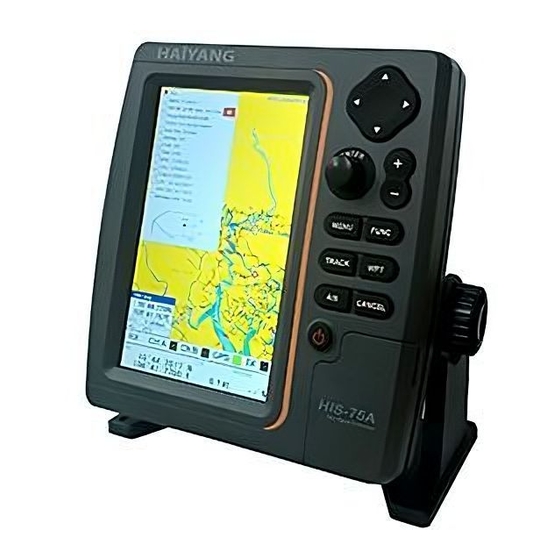
HIS-75A System HIS-75A Metal <Front> Main Screen Keypad Knob Mounting Bracket <Rear> Connector - 12 -... -
Page 17: His-75A Plastic
HIS-75A System HIS-75A Plastic <Front> Main Screen Keypad Knob Mounting Bracket <Rear> Connector - 13 -... -
Page 18: Spec Of The Connectors
HIS-75A System SPEC of the connectors Metal Plastic - 14 -... -
Page 19: Select Page
Page Select Page Press [Page] key and then go to “Pages” screen Selectable Pages by red box and then press [ENTER] key. red box - 15 -... -
Page 20: Customize
Customize Customize of screen Press [PAGE] key on the Pages which selected red box.(*Refer Fig. 1.1.1 as below) Select the layout of the formation of screen.(*Refer Fig. 1.1.2 as below) Select displays .(*Refer Fig. 1.1.3 & 1.1.4 as below) <Fig. 1.1.2> <Fig. -
Page 21: Customize Of Data Bar
Customize Customize of data bar ▶ [MENU]->Advance->Setup->Customizing->Data bar-> Edit Select the section to edit by red box. .(*Refer Fig. 1.2.1 as below) Press [ENTER] key and select the data as a user want.(*Refer Fig. 1.2.2 as below) Finish the formation of data bar, press [CANCEL] key to complete. <Fig. -
Page 22: Navigation Data Edit
Customize Navigation data edit ▶ [MENU]->Advance->Setup->Customizing->Navigation Data-> Edit Select the section to edit .(*Refer Fig. 1.3.1 as below) Press [ENTER] key and select the data as a user want. .(*Refer Fig. 1.3.2 as below) Finish the formation of data bar, press [CANCEL] key to complete (* If no navigation data on present activated display, it is not available to edit) <Fig. -
Page 23: Display
Display Chartplotter Scale AIS target Vessel icon Data bar - 19 -... -
Page 24: Highway
Display Highway Destination waypoint name Direction of Destination waypoint Vessel XTE Alarm Radius NAV. Information - 20 -... -
Page 25: Steering
Display Steering Destination waypoint name Direction of Destination waypoint NAV. Information - 21 -... -
Page 26: Gps Information
Display GPS Information Receiver status Satellite List Gain of Satellite - 22 -... - Page 27 AIS System AIS is an Automatic Identification System. It has been introduced to improve the safety of navigation by assisting in the efficient operation of ship to ship, ship reporting and VTS applications. The system should enable operators to obtain information from the ship automatically, requiring a minimum of involvement of ship‟s personnel, and should have a high level of availability.
- Page 28 AIS System 1. AIS system definitions Closest Point of Approach is the closest distance that will be achieved between your vessel and the tracked target, based on your vessel‟s speed and direction and the target‟s speed and direction. Occurs if CPA is less or equal to CPA Radius. This test is done for active targets CPA Alarm only.
- Page 29 AIS System 2. Quick info on AIS target Press [ENTER] key on Target which wants to see. It shows Information of “AIS INFO” window. AIS INFO window 1. Name 2. MMSI number 3. National 4. Navigation Status ※Press [ENTER] key on Target which wants to see. It shows Information of “AIS INFO”...
- Page 30 AIS MENU To obtain more information on AIS vessels or to configure the AIS ▶ Press [AIS] 1. AIS On/Off Turns the display of AIS targets overlay on the screen On or Off. (☞ The default setting is On.) 2. List of Vessels. Pressing the [ENTER] key will display a list of current AIS vessels inview.
- Page 31 5. Filter AIS types This function allows you to turn on or off reception from different types of AIS transmissions, for instance if you only wanted to view Class B vessels on the chart display then select Class B On and all the others Off.
- Page 32 8. Labels on vessels. This menu controls what details are displayed alongside the vessels icons on the chart display. 9. Cursor Box info. When you move the cursor in chart mode over an AIS target a box appears showing details of that vessel.
- Page 33 37 : Pleasure craft 50 : Pilot vessel 51 : Search and Rescue vessel 52 : Tugs 53 : Port Tenders 54 : Anti pollution vessel 55 : Law enforcement vessel 58 : Medical transport 60 : Passenger ship 70 : Cargo ship 80 : Tanker ship Continue to enter your vessels total length and breadth in the same manner.
- Page 34 Map Orientation 1. True Motion The True Motion is in the way the vessel position is presented. In True Motion mode, the vessel position symbol moves over the map while the map remains stationary. Select True motion. (* It is not available to operate on Course up and Head up.) 2.
- Page 35 Tide Information The HIS-70 series contains the tide information of principal place in the world ▶ Press [ENTER] [ The icon of the tide list ] [The window of the tide list] [ The window of the tide list ] - 31 -...
- Page 36 C - MAP It is to be used for Object information or Find function of C-MAP. ▶ Press [ENTER] 1. Information It is possible to see map information at the Vessel Position. (*Information is Port Services, Tides, Lights, Wrecks, Rocks, Buoys, Beacon, Obstructions, Land markers, etc.) 2.
- Page 37 Menu Menu It is available to load the window of the Menu on the activated chartplotter display in red box ▶ Press [MENU] 1. Userdata 1.1. WPT Waypoints may be entered and stored in the waypoint library by any of two different methods. You may use the cursor to select locations from a chart, or store vessel present position as a waypoint 1.1.1.
- Page 38 Menu 1.3-1.2. Setup 1.3-1.2.1. Thickness The size of a track is selectable between thin and pan. (☞ The default setting is Thin.) 1.3-1.2.2. Record setup Track display interval is adjustable by distance or time. (☞ The default setting is Time.) 1.3-1.2.3.
- Page 39 Menu 1.3.2-2.4. DIST interval If track interval is set in distance, a track displays by track distance interval. The track distance interval and the maximum capacity is 10,000 points. (☞ The default setting is 0.03nm.) 1.3.2-2.4. Track Type Setting up track type for type1 or type2. (☞...
- Page 40 Menu 5. WPT symbol You can select shape of WPT. (There are 16 sort of * WPT symbols as picture) 6. WPT color You can select the color of WPT symbol (There are 16 sort of * WPT symbols as picture) 7.
- Page 41 Menu 7.2. Next WPT It is available to set up a next WPT in the Present preferred route. 7.3. Route order It is available to set up the route forward and reverse in the Present route. preferred 7.4. Navigation Time Setting up navigation time for TTG or ETA during navigating.
- Page 42 - 38 -...
- Page 43 Advanced Menu Advanced Menu It is available to load the window of the Advanced Menu on the activated chartplotter display in red box ▶ Press [MENU] -> Advance 1. Map setting 1.1. Map orientation 1.1. True motion You can select “True motion” (☞...
- Page 44 Advanced Menu 1.6. LAT. Modification Though GPS information is accurate, there could be an error in the chart at latitude. The error can be modified in the chart latitude modification. 1.7. LOT. Modification Though GPS information is accurate, there could be an error in the chart at longitude. The error can be modified in the chart longitude modification.
- Page 45 Advanced Menu 1.8-2. C-Map (*Only for *C-MAP mode.) 1.8-2. 1. SAT.Image Setting up the overlay Satellite Image on the C-MAP. (☞ The default setting is shown.) 1.8-2. 2. Font&Symbols On charts it is possible to set the size of all names and symbols drawn on the charts, selecting between Normal size and Large size.
- Page 46 Advanced Menu 1.8-2. 7. QuickView It is available to set up. Place the cursor on buoys or icons on the C-MAP, the information window is shown up automatically. (☞ The default setting is hidden.) 2. Vessel 2.1. Vessel Icon Size The size of the present position is adjustable from 0 to 9.
- Page 47 Advanced Menu 3.2. Anchor 3.2.1. Anchor Alarm: It is necessary when your vessel anchors. (☞ The default setting is OFF.) 3.2.2. Anchor Radius: If you vessel is out of the range of the anchor, it gives you notice with alarm. (☞...
- Page 48 - 44 -...
- Page 49 General 1.GPS It is available to control and confirm information in GPS receiver. 1.1. Coordinate System It sets coordinate system of GPS or Loran. (☞The default setting is GPS.) 1.2. Datum It shows GPS Datum. WGS-84, which is the worldwide standard is only available. (☞...
- Page 50 General 2.Setup It is available to set the menu or units for user‟s visual confidence. 2.1. Unit 2.1.1. DIST/Speed Select desired unit of measure for distance and speed. Choose from: nautical mile/knots (nm/kt), kilometer/kilometers per hour(km/kmh), yard/knot(yd/kt). cf) 1nm = 1.852km, 1kt /h= 1.852km/h, less than 1nm display in yard and over 1nm display in mile (☞...
- Page 51 General 2.3.3. Date Format Sets you preferred date among YY-MM-DD, MM-DD-YY or DD-MM-YY. (☞ The default setting is YY-MM-DD.) 2.3.4. Month format Sets you preferred date between Character or Number. 2.3.5. Calendar setup 2.3.5.1. Week starts on You can select the first day of week. (☞...
- Page 52 General 2.4.4. Backlight time out It is the screen sets the time to sleep mode. (☞ The default setting is off.) 2.4.5. Customizing 2.4.5.1. Databar 2.4.5.1.1. Display Setting up shown/hide the databar on the display. (☞ The default setting is Shown.) 2.4.5.1.2.
- Page 53 General 3. Maintenance It is necessary to check the system or the version for maintenance and demonstrate HD-70 series with the simulators 3.1. Program VER. It contains ID and the program version, and it has important information for maintenance and upgrade. 3.2.
- Page 54 General 4. Others 4.1. Recording This is the function of recording current screen. Marked [● REC] in red color on the upper right on the data bar during recording. Note: The recording file is stored in SD card. (*The storage location is “E9\Recording\” in SD card). (* Recording time is different by the size of the memory card) 4.2.
- Page 55 Introduction How AIS Works The marine Automatic Identification System (AIS) is a location and vessel information reporting system. It allows vessels equipped with AIS to automatically and dynamically share and regularly update their position, speed, course and other information such as vessel identity with similarly equipped craft. Position is derived from a Global Navigation Satellite System (GNSS) network and communication between vessels is by Very High Frequency (VHF) digital transmissions.
- Page 56 Introduction Class A ship borne reporting intervals Ships dynamic conditions Rate Ship at anchor or moored 3 min Ship 0-14 Knots 10 sec Ship 0-14 Knots and changing course 3.3 sec Ship 14-23 Knots 6 sec Ship 14-23 Knots and changing course 2 sec Ship >...
- Page 57 NMEA 0183 Messages Receipt of a VHF transmission on either AIS radio channel causes a VDM message to be output via the data port. VDM Message Format !--VDM,x1,x2,x3,a,s--s,x*hh<CR><LF> x1 = Total number of sentences needed to transfer the message , 1 to 9 x2 = Sentence number, 1 to 9 x3 = Sequential message identifier, 0 to 9 a = AIS Channel, "A"...
- Page 58 NMEA 0183 Messages yyyyy.yy,a1 = Region Northeast corner longitude – E/W llll.ll,a = Region Southwest corner latitude – N/S y1y1y1y1y1.y1y1,a2 = Region Southwest corner longitude – E/W x1 = Transition Zone Size x2x2x2x2 = Channel A x3 = Channel A bandwidth x4x4x4x4 = Channel B x5 = Channel B bandwidth x6 = Tx/Rx mode control...
- Page 59 ACK Message Format Can be generated by a minimum keypad and display (MKD) unit, chart plotter or other display device connected to the HIS-75A to acknowledge an alarm condition reported by the SAS SERIES. $--ACK,xxx*hh <CR><LF> xxx = Unique alarm number...
- Page 60 Installation GPS Antenna The GPS antenna used must be of the active type (i.e. it should incorporate an LNA) and must be suitable for marine shipboard applications (index of protection, ruggedness, means of mounting, etc.). An antenna should be selected with a gain (in dB) depending on the length of cable between the antenna and the AIS unit;...
- Page 61 Installation shorting the VHF antenna port will activate the VSWR alarm, cause the unit to stop sending position reports or cause damage to the transponder. Radio Frequency Exposure To meet the requirements for Radio Frequency Exposure it is necessary to install the VHF antenna correctly and operate the AIS equipment according to the instructions.
- Page 62 The display unit is designed to be mounted on either a console or from an overhead surface. The HIS-75A display is also designed for flush mounting using six threaded holes on the rear panel. Locate the display in an area with protection from the elements and avoid direct sunlight on the viewing window.
- Page 63 - Power Connection Power is supplied to the HIS-75A System through a connector on the rear panel of the display unit. Route the power cable from the HIS-75A location to the ship‟s power distribution panel.
- Page 64 Reference - Care and Cleaning Your HIS-75A is made to withstand marine elements but a little care ensures a trouble free life. Accumulations of salt and sand, if not removed, will eventually mar the finish. No solvents or harsh cleaners should be used. The display unit may be wiped down with a damp cloth while avoiding the display window.
- Page 65 For centuries, sailors haven en searching for a reliable and precise method of travelling the world‟s waterways. From celestial navigating to the modern navigation techniques as Loran, Decca navigator, Omega or Transit Satnav, each system has had its problems with weather, range and reliability. Without doubt, the “Global Positioning System”, or GPS for short, is the most significant advance in navigation: it fives the navigator a position 24 hours a day, 365 days a year in any weather condition.
- Page 66 The position calculation procedure is indicated in the following three steps: 1. GPS satellites continuously transmit their own precise orbital data and the GPS receiver computes their locations by receiving this data. 2. In this receiving process, the GPS receiver measures very accurate distances to the satellites, using the "Spread Spectrum Modulation"...
- Page 67 The installation of the GPS ANT. The GPS ANT must be installed at the highest area of the boat and the easiest place to catch the signal from the satellites. If there are obstacles around the GPS ANT, it isn't able to catch all signals. The receiving time would be longer or the receiving power would be weaker.
- Page 68 - 64 -...
- Page 69 - 65 -...
- Page 70 - 66 -...
- Page 71 - 67 -...
- Page 72 - 68 -...
- Page 73 - 69 -...
- Page 74 - 70 -...
- Page 75 Web-site: http://www.haiyang.co.kr Guarantee for One Year Haiyang Electronic Equipment Co., LTD warrants the produced equipment, Equipment for One (1) year for guarantee as bellows. 1. Main Unit: One (1) year guarantee after a user purchases the product within one (1) year 2.
Need help?
Do you have a question about the HIS-75A and is the answer not in the manual?
Questions and answers