
Related Manuals for Datalogic QuickScan QM2430


Summary of Contents for Datalogic QuickScan QM2430
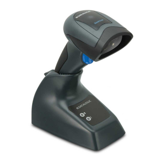
- Page 1 QuickScan™ QM2400 General Purpose Handheld Area Imager Bar Code Reader with Datalogic’s STAR Cordless System™ Quick Reference Guide...
- Page 2 Datalogic has taken reasonable measures to provide informa- tion in this manual that is complete and accurate, however, Datalogic reserves the right to change any specification at any time without prior notice. Datalogic and the Datalogic logo are registered trademarks of Datalogic S.p.A.
-
Page 3: Table Of Contents
Charging the Batteries ..............8 Replacing the Battery Pack ..........9 Using the Quickscan™ QM2400 ..........10 Linking the Reader ..............11 Link Datalogic RF Devices to Base......11 Power Off ..................11 Programming ................11 Using Programming Bar Codes ........12 Configure Other Settings .......... - Page 4 Warranty Claims Process........38 Warranty Exclusions..........39 No Assignment ............40 Risk of Loss .............. 40 Ergonomic Recommendations ..........41 Cleaning ................42 Support Through the Website ..........43 QuickScan™ QM2400...
-
Page 5: End User Software License Agreement (Eula)
1.1 Datalogic grants to End User, a personal, non-exclusive, non-transferable, non sub licensable, revocable, limited license to use the Software, solely on the Datalogic Product in which it is embedded or for which it is intended for use, in machine-readable form only, solely for End User's internal business purposes. - Page 6 Software is used with the Datalogic Product. Datalogic' s entire liability and End User' s sole and exclusive remedy for any breach of the foregoing limited warranty will be, at Datalogic' s option, the pro- vision of a downloadable patch or replacement software.
- Page 7 Notices to Datalogic shall be sent to the attention of Datalogic IP Tech S.r.l., Legal & IP Department, Via San Vitalino 13, 40012 Calderara di Reno (Bologna), Italy, or such other address as may be specified by Datalogic in writing.
-
Page 8: Software Product Policy
Italy, without regard to the rules governing conflicts of law. Italian Court of Bologna shall have exclusive jurisdiction over all matters regarding this Agreement, except that Datalogic shall have the right, at its absolute discretion, to initiate proceedings in the courts of any other state, country, or territory in which End User resides, or in which any of End User's assets are located. -
Page 9: Description
QuickScan™ QM2400 Description With rich feature sets and extensive options, the QuickScan™ product series from Datalogic represents the premium level of data collection equipment for general purpose applications. The QuickScan QM2400 readers have enhanced optics with improved motion tolerance allowing codes placed on fast... -
Page 10: Setting Up The Reader
Setting Up the Reader Setting Up the Reader Follow the steps below to connect and get your reader up and communicating with its host. Configure the Base Station starting on this page. Charge the Batteries (see page 8). Link to the Base Station (see page 11). Select the Interface Type (see page 13). - Page 11 Setting Up the Reader Figure 1. Lock lever disengaged Engage the locking mechanism by pushing up the lever as far as it will go. Figure 2. Lever in locked position It is good practice to put the scanner in the locked condition at the end of the working shift, or when not in use for an extended period of time.
-
Page 12: Connecting The Base Station
Connecting the Base Station Connecting the Base Station Figure 3 shows how to connect the Base Station to a termi- nal, PC or other host device. Turn off the host before connec- tion and consult the manual for that equipment (if necessary) before proceeding. - Page 13 Connecting the Base Station After the cables are plugged in, reinsert the rubber Cable Stopper. Cable Stopper reinserted Connect to an AC Adapter, and plug the AC power cord into the (wall) outlet. Figure 3. Connecting the Base Station Wall plug Connector I/F Cable AC/DC...
-
Page 14: System And Network Layouts
Connecting the Base Station Figure 4. Connecting to the Host or... or... or... Power Connection — Plug the AC Adapter into an approved AC wall socket with the cable facing downwards (as shown in Figure 3) to prevent undue strain on the socket. System and Network Layouts Stand Alone Layout Figure 5. -
Page 15: Using The Bc2030™ Radio Base
Connecting the Base Station Using the BC2030™ Radio Base Radio Base LEDs LEDs on the QuickScan Base provide information about the Base as well as battery charging status, as shown in Figure Figure 6. QuickScan Base LEDs Red LED / Green LED Yellow LED Table 1. -
Page 16: Charging The Batteries
Charging the Batteries Charging the Batteries To charge the battery, simply insert the QuickScan reader into the base. When the scanner is fully seated in the cradle, it will sound a “chirp” to indicate that the cradle has detected the scanner connection. -
Page 17: Replacing The Battery Pack
Charging the Batteries Replacing the Battery Pack Before proceeding, read “Battery Safety” in the Regulatory Addendum for this manual. Datalogic recommends annual replacement of rechargeable battery packs to ensure maxi- NOTE mum performance. Using a coin or a screwdriver, unscrew the captive screw located on the bottom of the battery pack until it is disengaged. -
Page 18: Using The Quickscan™ Qm2400
LED indicator. Reference the QuickScan QM2400 Product Reference Guide (PRG) on the Datalogic website for more information about this feature and other programmable settings. QuickScan™ QM2400... -
Page 19: Linking The Reader
Data Editing and Symbologies chapters. The reader can also be configured with Datalogic Aladdin™ software (available on the Datalogic website). Aladdin pro- vides RS-232 interface configuration, as well as bar code printing. -
Page 20: Using Programming Bar Codes
Programming Using Programming Bar Codes This manual contains bar codes which allow you to reconfig- ure your reader. Some programming bar code labels, like the "Standard Product Default Settings" on page 12, require only the scan of that single label to enact the change. Other bar codes require the reader to be placed in Program- ming Mode prior to scanning them. -
Page 21: Selecting The Base Interface Type
Selecting the Base Interface Type Selecting the Base Interface Type Upon completing the physical connection between the base and its host, proceed directly to Interface Selection (below) for information and programming for the interface type the base is connected to (for example: RS-232, Keyboard Wedge, USB, etc.) and scan the appropriate bar code to select your sys- tem’s correct interface type. - Page 22 RS-232 Wincor-Nixdorf Select RS232-WN RS-232 for use with OPOS/UPOS/JavaPOS Select RS-232 OPOS USB COM to simulate RS-232 standard interface Select USB-COM-STD USB-OEM USB-OEM (can be used for OPOS/UPOS/JavaPOS) Select USB-OEM a. Download the correct USB COM driver from www.datalogic.com QuickScan™ QM2400...
-
Page 23: Keyboard Interface
Selecting the Base Interface Type Keyboard Interface Use the programming bar codes to select options for USB Keyboard and Wedge Interfaces. KEYBOARD AT, PS/2 25-286, 30-286, 50, 50Z, 60, 70, 80, 90 & 95 w/ Standard Key Encoding Select KBD-AT Keyboard Wedge for IBM AT PS2 with standard key encoding but without external keyboard Select KBD-AT-NK... - Page 24 Selecting the Base Interface Type KEYBOARD (continued) PC/XT w/Standard Key Encoding Select KBD-XT Keyboard Wedge for IBM Terminal 3153 Select KBD-IBM-3153 Keyboard Wedge for IBM Terminals 31xx, 32xx, 34xx, 37xx make only keyboard Select KBD-IBM-M Keyboard Wedge for IBM Terminals 31xx, 32xx, 34xx, 37xx make break keyboard Select KBD-IBM-MB USB Keyboard with alternate key encoding...
-
Page 25: Scancode Tables
Selecting the Base Interface Type KEYBOARD (continued) USB Keyboard for Apple computers Select USB-KBD-APPLE Keyboard Wedge for DIGITAL Terminals VT2xx, VT3xx, VT4xx Select KBD-DIG-VT USB Keyboard with standard key encoding Select USB Keyboard Scancode Tables Reference the QuickScan QM2400 ™ PRG for information about control character emulation which applies to keyboard interfaces. - Page 26 Selecting the Base Interface Type All other interfaces support ONLY the following Country Modes: U.S., Belgium, Britain, France, Germany, Italy, Spain, Sweden. COUNTRY MODE ENTER/EXIT PROGRAMMING MODE Country Mode = U.S. Country Mode = Belgium Country Mode = Britain Country Mode = Croatia* *Supports only the interfaces listed in the Country Mode feature description QuickScan™...
- Page 27 Selecting the Base Interface Type COUNTRY MODE (continued) Country Mode = Czech Republic* Country Mode = Denmark* Country Mode = France Country Mode = Germany Country Mode = Hungary* Country Mode = Italy *Supports only the interfaces listed in the Country Mode feature description Quick Reference Guide...
- Page 28 Selecting the Base Interface Type COUNTRY MODE (continued) Country Mode = Japanese 106-key* Country Mode = Norway* Country Mode = Poland* Country Mode = Portugal* Country Mode = Romania* Country Mode = Spain *Supports only the interfaces listed in the Country Mode feature description QuickScan™...
- Page 29 Selecting the Base Interface Type COUNTRY MODE (continued) Country Mode = Sweden Country Mode = Slovakia* Country Mode = Switzerland* *Supports only the interfaces listed in the Country Mode feature description Quick Reference Guide...
-
Page 30: Caps Lock State
Selecting the Base Interface Type Caps Lock State This option specifies the format in which the reader sends character data. This applies to keyboard wedge interfaces. This does not apply when an alternate key encoding keyboard is selected. ENTER/EXIT PROGRAMMING MODE Caps Lock State = Caps Lock OFF Caps Lock State = Caps Lock ON Caps Lock State = AUTO Caps Lock Enable... -
Page 31: Numlock
Selecting the Base Interface Type Numlock This option specifies the setting of the Numbers Lock (Num- lock) key while in keyboard wedge interface. This only applies to alternate key encoding interfaces. It does not apply to USB keyboard. ENTER/EXIT PROGRAMMING MODE Numlock = Numlock key unchanged Numlock = Numlock key toggled Quick Reference Guide... -
Page 32: Reading Parameters
Reading Parameters Reading Parameters Point the reader at the target and pull the trigger to enable the aiming system and the illuminator (red beam) to decode the bar code label. The aiming system will briefly switch off during the acquisition time and if no code is decoded will switch on again before the next acquisition. -
Page 33: Good Read Green Spot Duration
Reading Parameters Good Read Green Spot Duration Successful reading can be signaled by a good read green spot. Use the bar codes below to specify the duration of the good read pointer beam after a good read. ENTER/EXIT PROGRAMMING MODE Green Spot Duration = Disable (Green Spot is Off) Green Spot Duration = Short (300 msec) Green Spot Duration = Medium (500 msec) -
Page 34: Scan Modes
Scan Modes Scan Modes The imager can operate in one of several scanning modes. Trigger Single — When the trigger is pulled, scanning is acti- vated until one of the following occurs: • a programmable duration has elapsed • a label has been read •... - Page 35 Scan Modes SCAN MODE ENTER/EXIT PROGRAMMING MODE Scan Mode = Trigger Single Scan Mode = Trigger Hold Multiple Scan Mode = Trigger Pulse Multiple Scan Mode = Flashing Scan Mode = Always On Scan Mode = Stand Mode Quick Reference Guide...
-
Page 36: Pick Mode
Scan Modes Pick Mode Pick Mode is a Decoding and Transmission process where bar codes that are not within the configurable distance from the center of the aiming pattern are not acknowledged or trans- mitted to the host. It is active only while the scanner is in Trigger Single mode. -
Page 37: Technical Specifications
Technical Specifications Technical Specifications The following table contains Physical and Performance Char- acteristics, User Environment and Regulatory information. Physical Characteristics Color White or Black Height 6.4”/163 mm Dimensions Length 3.6”/91 mm Width 1.6”/41 mm Approximately Weight (without cable) 200 g (reader) 230 g (base charger) Electrical Characteristics Battery Type... - Page 38 Technical Specifications Performance Characteristics Light Source LEDs Roll (Tilt) Angle Up to ± 180° Pitch Angle ± 40° Skew (Yaw) Angle ± 40° Field of View 40° H x 26° V a. Charge Times are much lower when battery is within daily typical operating condition.
- Page 39 Code 128; Code 128 ISBT; Interleaved 2 of 5; Standard 2 of 5; Inter- leaved 2 of 5 CIP (HR); Industrial 2 of 5; Discrete 2 of 5; Datalogic 2 of 5 (China Post Code/Chinese 2 of 5); IATA 2of5 Air cargo code;...
- Page 40 Technical Specifications User Environment Operating Tem- 32° to 122° F (0° to 50° C) perature Charging Tempera- 32° to 104° F (0° to 40° C) ture Storage Tempera- -4° to 158° F (-20° to 70° C) ture Operating: 5% to 90% relative humidity, Humidity non-condensing Scanner withstands 18 drops from 1.5...
-
Page 41: Led And Beeper Indications
LED and Beeper Indications LED and Beeper Indications The reader’s beeper sounds and its LED illuminates to indi- cate various functions or errors on the reader. An optional “Green Spot” also performs useful functions. The following tables list these indications. One exception to the behaviors listed in the tables is that the reader’s functions are program- mable, and so may or may not be turned on. - Page 42 LED and Beeper Indications Indication Description Beeper Upon successful read of a label, Green Spot the software flashes shall turn the momentar- green spot on for the time specified by the configured value. Except when in sleep mode or when a Good Read LED Duration other than 00 is selected Programming Mode - The following indications ONLY occur when...
-
Page 43: Error Codes
Error Codes Error Codes Upon startup, if the reader sounds a long tone, this means the reader has not passed its automatic Selftest and has entered FRU (Field Replaceable Unit) isolation mode. If the reader is reset, the sequence will be repeated. The following table describes the LED flashes/beep codes associated with an error found. -
Page 44: Datalogic Limited Factory Warranty
Datalogic (“Datalogic”) hardware products are warranted against defects in material and workmanship under normal and proper use. The liability of Datalogic under this warranty is limited to furnishing the labor and parts necessary to rem- edy any defect covered by this warranty and restore the prod- uct to its normal operating condition. -
Page 45: Warranty Exclusions
Datalogic shall pay for the return of the product to Customer if the shipment is to a loca- tion within the country in which the Datalogic service center is located. Customer shall be responsible for paying all shipping charges, duties, taxes, and any other charges for products returned to any other locations. -
Page 46: No Assignment
No attempted assignment or transfer in violation of this provision shall be valid or binding upon Datalogic. DATALOGIC' S LIMITED WARRANTY IS IN LIEU OF ALL OTHER WARRANTIES, EXPRESS OR IMPLIED, ORAL OR WRITTEN, STATUTORY OR OTHERWISE, INCLUDING, WITHOUT LIMITA- TION, ANY IMPLIED WARRANTIES OF MERCHANTABILITY, FIT- NESS FOR A PARTICULAR PURPOSE, OR NONINFRINGEMENT. -
Page 47: Ergonomic Recommendations
Ergonomic Recommendations Ergonomic Recommendations To avoid or minimize potential risk of ergo- nomic injury follow the recommendations below. Consult with your local Health & Safety Manager to ensure you are adhering to your company’s safety programs prevent CAUTION employee injury. •... -
Page 48: Cleaning
Ergonomic Recommendations Cleaning Exterior surfaces and scan windows exposed to spills, smudges or debris require periodic cleaning to ensure best performance during scanning. Contacts on the scanner and base should also be cleaned as needed to ensure a good con- nection. -
Page 49: Support Through The Website
Support Through the Website Support Through the Website Datalogic provides several services as well as technical sup- port through its website. Log on to www.datalogic.com and click on the SUPPORT > General Duty Handheld Scanners category link. From this page you can select your product model from the dropdown... - Page 50 Support Through the Website NOTES QuickScan™ QM2400...
- Page 52 959 Terry Street | Eugene, OR 97402 |USA Telephone: (541) 683-5700 | Fax: (541) 345-7140 ©2014-2017 Datalogic S.p.A. and/or its affiliates. All rights reserved. Datalogic and the Datalogic logo are registered trademarks of Datalogic S.p.A. in many countries, including the U.S.A. and the E.U.
Need help?
Do you have a question about the QuickScan QM2430 and is the answer not in the manual?
Questions and answers