Table of Contents
Advertisement
Quick Links
FSM-6228G Ethernet Switch QuickStart v1.0
This document provides quick installation on FSM-6228G series
Package Checklist
Please verify that the box contains the following items:
Item
Rack-mount Ethernet switch
Rack-mount bracket
Screws (for bracket)
DC power terminal block (4-pin) – option for DC models
ALM terminal block (2-pin)
Quick Installation Guide
RJ45 Ethernet port Dust Cover
SFP Ethernet port Dust cover
Safety Instructions
When a connector is removed during installation, testing, or servicing, or when an energized fiber
is broken, a risk of ocular exposure to optical energy that may be potentially hazardous occurs,
depending on the laser output power.
The primary hazards of exposure to laser radiation from an optical-fiber communication system
are:
Damage to the eye by accidental exposure to a beam emitted by a laser source.
Damage to the eye from viewing a connector attached to a broken fiber or an energized fiber.
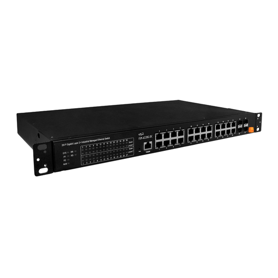
Model Layouts
Front Access Models
www.ipc2u.ru
. It contains:
Quantity
1
2
6
1
1
1
14
2
1
www.moxa.pro
Advertisement
Table of Contents

Subscribe to Our Youtube Channel
Related Manuals for ICP DAS USA FSM-6228G


Summary of Contents for ICP DAS USA FSM-6228G
- Page 1 FSM-6228G Ethernet Switch QuickStart v1.0 . It contains: This document provides quick installation on FSM-6228G series Package Checklist Please verify that the box contains the following items: Item Quantity Rack-mount Ethernet switch Rack-mount bracket Screws (for bracket) DC power terminal block (4-pin) – option for DC models...
- Page 2 Front View All Front Access models Rear View FSM-6228G-DC FSM-6228G-AC www.ipc2u.ru www.moxa.pro...
- Page 3 Front view -Front Access Model Rear view - Rear Access Model Rear view - Front Access Model System Status Indicators (LED) Port Status Indicators (LED) Gigabit Copper RJ45 ports ...
- Page 4 Rack Mounting When mounting the switch, practice good safety habits. Relay rack mounting normally requires at least two people. 1. Obtain the tools required for the mounting hardware. 2. Attach the mounting brackets to the switch by using the screws in the accessory kit. Position 1 Position 2 3.
- Page 5 Mounting Bracket Position 2 for Standard Mount Ground Connecting IMP-528/828 must be properly grounded for optimum system performance. Alarm Relay Connecting The alarm relay output contacts with current carrying capacity of 30VDC, 1A are a 2P terminal block. The alarm relay contact is “Normal Open”, and it will be closed when detected any power failures. Power Connecting DC Power Connection The switch can be powered from two power supply (input range 12V –...
- Page 6 AC Power Connection If you use AC power, connect the AC power cord to the AC supply socket on the rear panel, and plug the cord into the external power source. The voltage must be 100 to 240 V (±10% tolerance). Warning: Ensure that all power sources to the chassis (power distribution panel) are turned off during the connection.
- Page 7 Console Connection The Console port is for local management by using a terminal emulator or a computer with terminal emulation software. DB9 connector connect to computer COM port Baud rate: 115200bps 8 data bits, 1 stop bit ...
- Page 8 CLI Initialization & Configuration (Optional) Connecting to IMP-528/828 Ethernet port (RJ45 Ethernet port). Key-in the command under Telnet: telnet 192.0.2.1 Login with default account and password. Username: admin Password: admin Change the IP with commands listed below: CLI Command: enable configure interface vlan 1 ip-address xxx.xxx.xxx.xxx netmask xxx.xxx.xxx.xxx...
Need help?
Do you have a question about the FSM-6228G and is the answer not in the manual?
Questions and answers